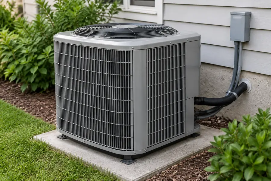
Quick answer: For a wall-mounted ductless mini split, proper installation starts with a manufacturer-approved, correctly sized indoor-and-outdoor unit combination and suitable mounting locations. Qualified installers then route the refrigerant lines, drain and electrical connections safely, and check refrigerant tightness, electrical safety, drainage and operation. A unit turning on alone does not prove the job is complete.
Follow the exact model installation manual and local requirements. Serving several rooms, providing primary winter heating, using a drain pump or upgrading the electrical supply can change the installation plan and required tests.
What does a proper split air conditioner installation involve?
A proper split air conditioner installation starts with the right system and location. The installer then mounts the units, routes the refrigerant lines and drain, completes the electrical connections, and tests the finished system. Ask for the test results and operating instructions before the job is handed over. Changing the thermostat cannot fix an undersized system or a bad pipe route.
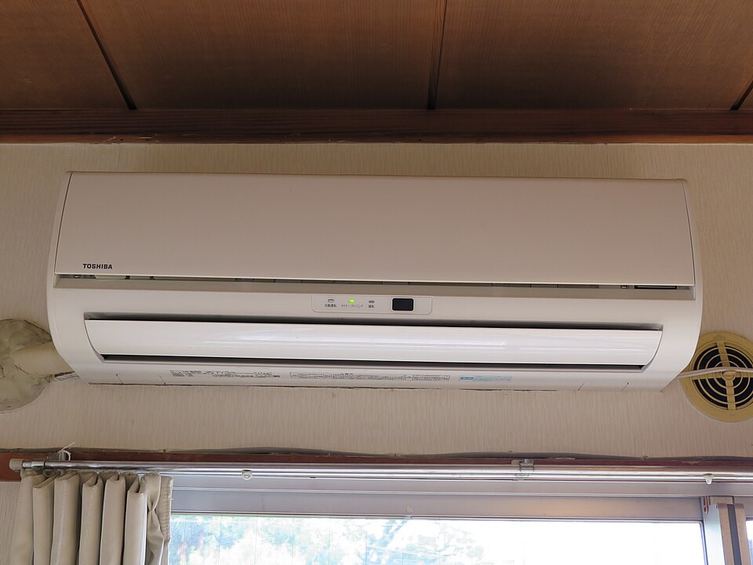
A ductless mini split usually has one outdoor unit and one or more wall-mounted indoor units. Refrigerant—the fluid that carries heat—flows through pipes between them. An indoor fan moves room air across a coil (the heat exchanger), and a separate drain removes water produced during cooling. A ducted split system also has indoor and outdoor equipment, but it distributes air through ducts. This guide mainly covers wall-mounted ductless installations, with extra points for multi-zone and ducted systems.
| Step | What to get right | What to ask for |
|---|---|---|
| Choose the system | Heating/cooling loads, matched models, electrical supply and zones | Room load calculation and selected model numbers |
| Check the site | Airflow, access, secure mounting and drainage | Marked locations and the model’s required clearances |
| Connect the equipment | Approved refrigerant pipes, sealed wall openings and safe wiring | Equipment-specific piping/electrical plan and any required inspection |
| Test and hand over | Passed leak and drying checks; correct charge and operation | Test records, running measurements and user instructions |
Can you install a mini split air conditioner yourself?
You can measure rooms and help plan where a mini split might go, but do not assume you can install the whole system yourself. Refrigerant work can trigger U.S. EPA Section 608 certification requirements, including work that opens the circuit; a limited supervised-apprentice exception applies under the EPA rules. Electrical work, permits and contractor licensing also depend on local law. Check those rules before starting.
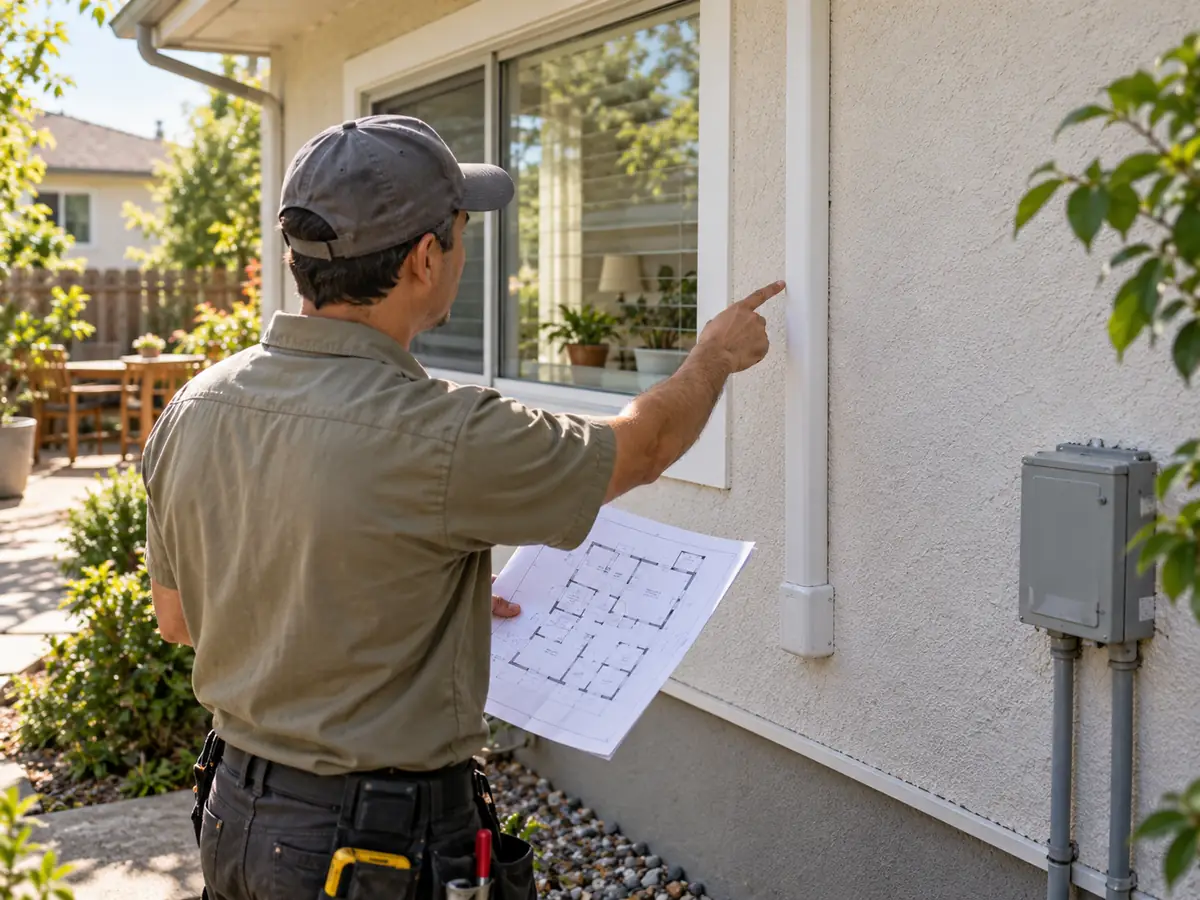
Risk — A “DIY mini split” label does not mean every connection is legal to make yourself. The U.S. EPA says that connecting or disconnecting hoses or pre-charged lines on an R-410A mini split requires Section 608 technician certification. Follow the actual kit instructions and your local rules. Never vent refrigerant, open sealed connections without the required qualifications, improvise pipe joints, or copy electrical connections from an unrelated online diagram.
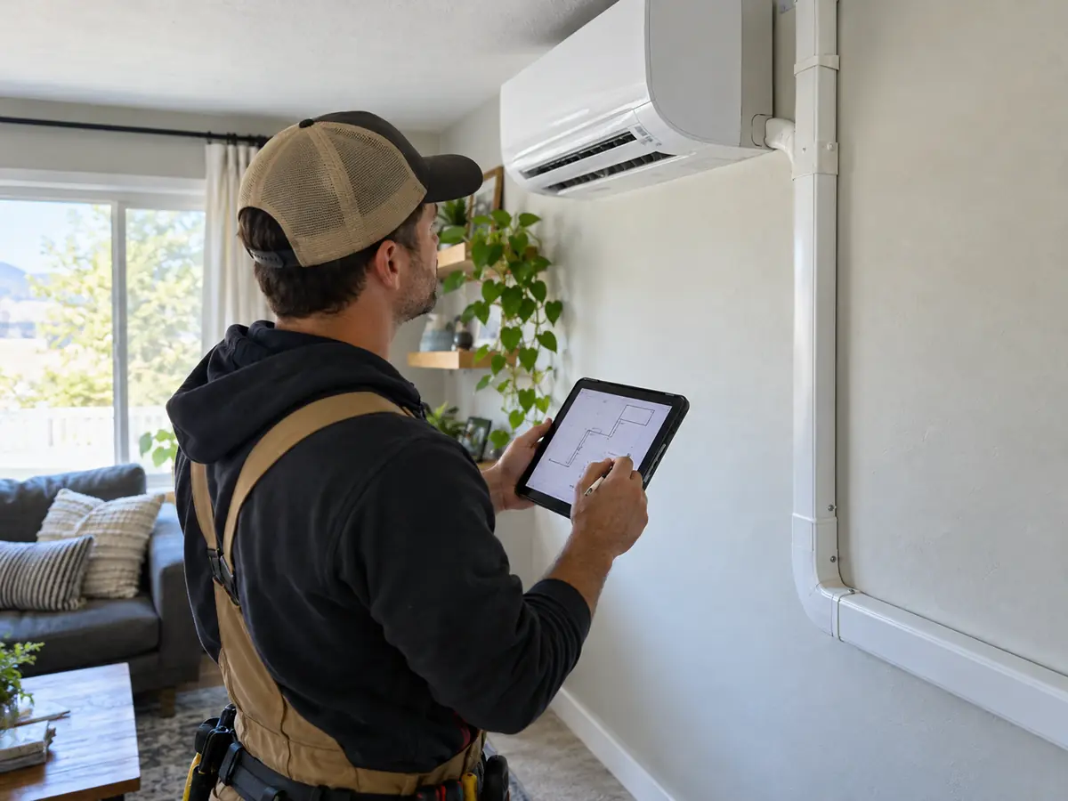
Before the crew arrives, you can measure the rooms, photograph possible unit locations and arrange access. If you see damaged wiring, loose supports, a suspected refrigerant leak or water near electrical parts, stop work and have a qualified person make the area safe. Do not power an unchecked system.
Before work begins, confirm who does what:
- You or the property manager: Provide room details and obtain owner, landlord or association approval when required.
- The installer: Confirm the matched equipment, mounting points, pipe and drain routes, and what startup checks will be recorded.
- The appropriate licensed trade: Confirm who obtains permits, arranges required inspections, and performs regulated electrical or refrigerant work under applicable law.
What must be checked before installation starts?
Before installation, check how much heating and cooling each room needs (its design load) and whether the exact indoor and outdoor models are approved to work together. Then confirm there is enough room for the pipes, drain, power supply, outdoor airflow and service access. The site may also need extra safety measures for the refrigerant used. An empty wall space alone does not prove the unit is suitable.
Two rooms of the same size can need different cooling capacities. Sun exposure, window area, insulation, air leaks, people and appliances all change the heat entering a room. If the system will also provide the main heating, calculate the heating need as well. In the U.S., ACCA Manual J is a recognized way to calculate these room and building loads. Manual S helps select actual equipment that meets them, including ductless single- and multi-zone systems. Do not choose a “12,000 BTU” model from floor area alone: its nominal rating may differ from its capacity in your hottest or coldest design conditions.
Cooling load has two parts: sensible load is the heat that raises room temperature; latent load is the moisture the system must remove. In a humid climate, compare both with the selected unit’s published cooling performance where those data are available. A system that cools the air may still leave the room damp if moisture removal or part-load operation is unsuitable.
A nominal capacity label describes a rating, not guaranteed output at your site. Compare the room loads with the manufacturer’s published heating and cooling output for the approved indoor/outdoor combination at local design temperatures and relevant operating settings. Where manufacturer data permit, also check its lowest stable output against light-load conditions. Oversizing can cause unnecessary cycling or poor moisture control even when peak cooling is sufficient; installation quality and controls still affect actual room comfort.
If the system is the primary heater, check the published heating output at the local winter design temperature, the manufacturer’s guidance for defrost and cold-weather operation, and the building’s heating load at that same condition. A stated minimum operating temperature only means operation is permitted under specified conditions; it does not prove the unit can heat the building on its own. Record whether supplemental heat is needed. If you are still deciding between cooling-only air conditioning and a reversible heat pump, compare their heating functions and design-condition requirements before selecting a model.
Use this pre-installation check to expose issues that change the layout:
- Equipment — Check that the exact indoor and outdoor model numbers, branch parts and controls are approved to work together.
- Location — Confirm the required airflow space, safe service access, structural support and protection from outdoor weather.
- Refrigerant pipes — Compare pipe diameter, full route length, height difference, any minimum length, insulation and bends with the exact manual.
- Drainage — Confirm water can flow continuously downhill to an allowed outlet. If not, check whether a suitable condensate pump and overflow protection are needed.
- Power and permits — Match voltage, phase, frequency, circuit capacity, overcurrent protection (the breaker or fuse), disconnect and permit requirements to the equipment and local code.
- Refrigerant safety — Check whether the refrigerant type and amount require room-size limits, ventilation, ignition-source controls or other measures under the product listing, code and manual.
For example, a room on the far side of the building may need a longer line set, an uphill drain route and extra electrical work. If any one of those falls outside the model’s limits or the site’s legal requirements, the answer is to revise the unit locations, drainage design or equipment plan before drilling—not to force the original route.
Check the refrigerant designation on the exact unit’s nameplate. If the system uses a refrigerant with additional safety requirements, ask the installer to show which room-size, piping, ventilation, leak-detection or ignition-source provisions apply under that model’s listing, instructions and local code. Do not copy the safety arrangement from a different refrigerant or model. For installations in the United States, the U.S. mini split equipment guide explains how to check the exact indoor/outdoor model combination and efficiency or incentive documentation relevant to the project.
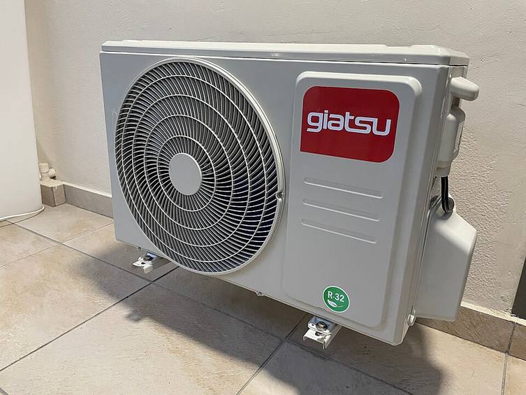
Before drilling any holes, ask for the manuals for your exact indoor and outdoor models, the room load calculation, a route sketch and the electrical ratings on the unit’s nameplate (the manufacturer’s identification label). If no one can show the specified pipe sizes, length limits, breaker requirements or clearances, stop and check them. There is no single set of installation dimensions that fits every split AC.
Where should the indoor unit be installed?
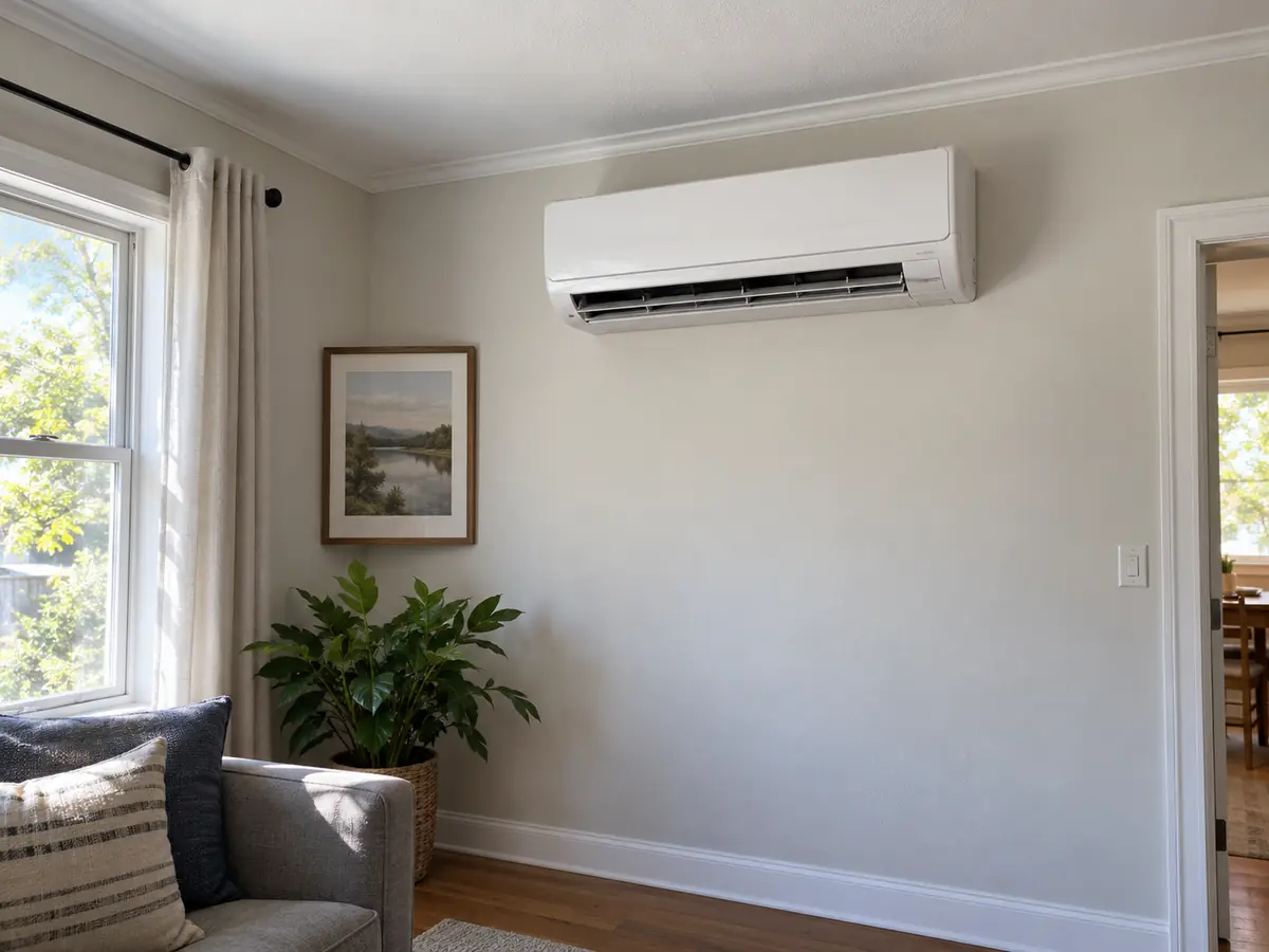
Put the split air conditioner indoor unit on a structurally suitable surface where it can circulate air across the intended zone, drain condensate safely, and remain accessible for cleaning and service. Avoid positions where supply air blows directly onto occupied seating for long periods or is immediately blocked by a beam, cabinet or curtain.
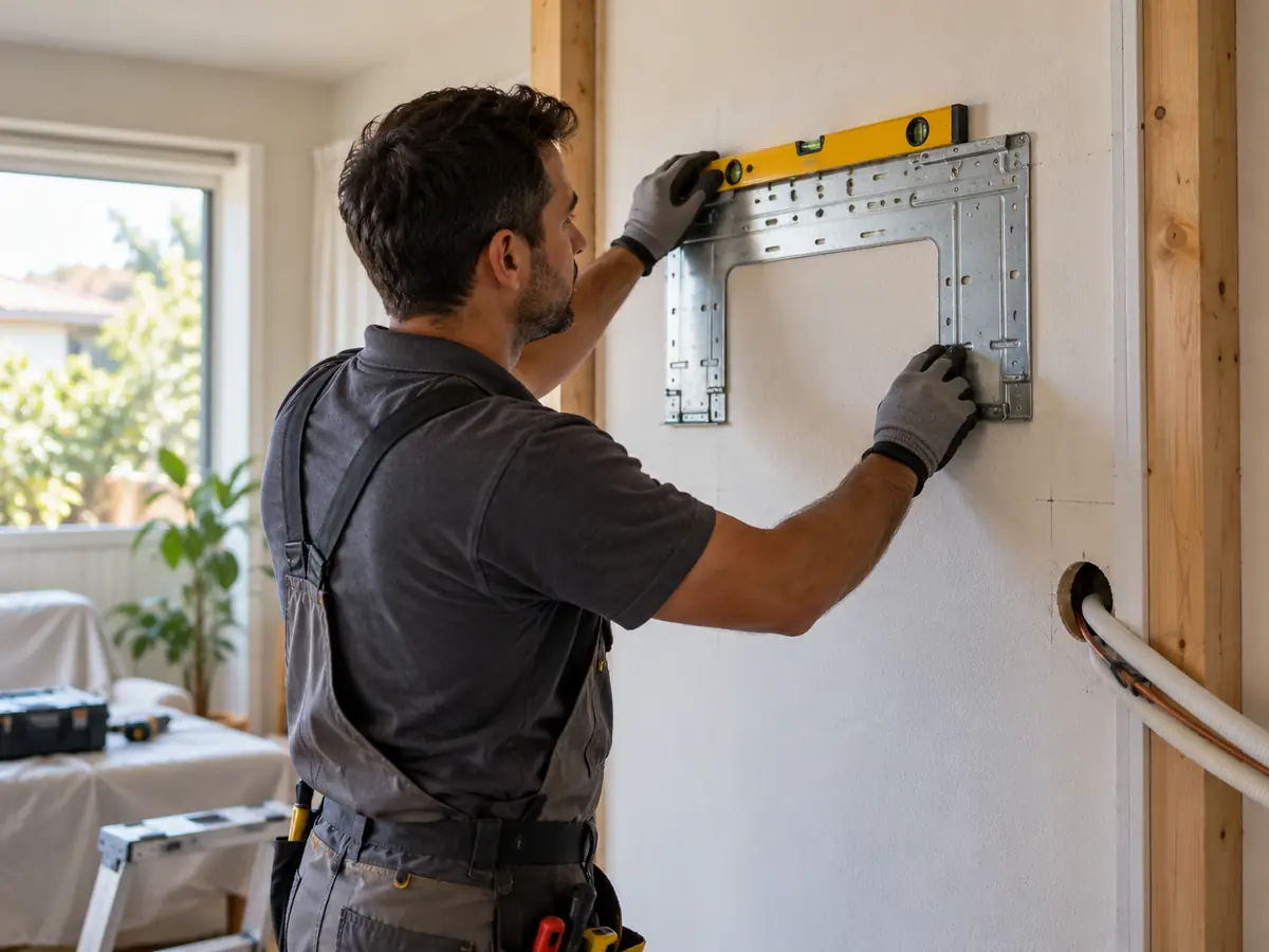
For a wall-mounted unit, the mounting plate must be level and secured to the specified supporting structure. Do not assume drywall alone can carry the assembly. Position matters for both comfort and drainage: a long, obstructed throw can leave part of the room warm, while a drain that rises, sags or has trapped sections can back up and cause leaks. Follow the unit-specific mounting, leveling and drain-slope rules rather than using a generic installation height.
Leave enough room to remove the indoor unit’s filter and service cover; a neat-looking position above furniture is not useful if the unit cannot be cleaned. Ceiling cassettes and concealed ducted indoor units also need ceiling access, a safe drain route and enough return air. For ducted units, check external static pressure (ESP)—how much resistance the fan can overcome in the ductwork. Confirm noise and airflow settings in the real room. Clear space cannot make up for choosing the wrong capacity.
Check where the selected model senses room temperature—at the indoor return air, a wall controller or another approved sensor. High mounting positions, direct sun, nearby heat sources and blocked return air can make the measured temperature differ from the occupied part of the room. Confirm the approved control location and compare actual room comfort with the controller reading during commissioning.
Where should the outdoor unit be placed?
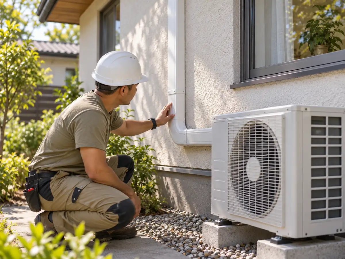
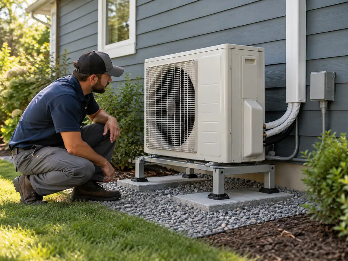
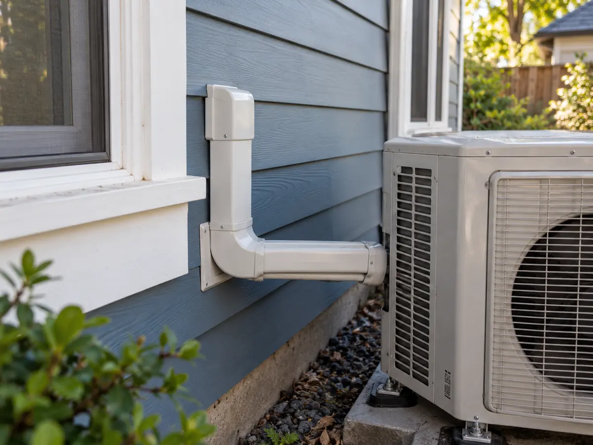
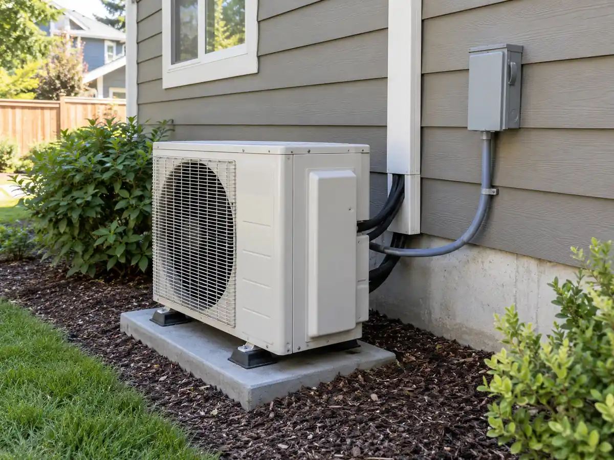
Install the outdoor unit on a level, secure support that can withstand local outdoor conditions, including corrosion where relevant. Leave the airflow, drainage and service space required for the exact model. Keep exhaust air from recirculating into the intake, and assess noise and vibration at neighboring windows and occupied areas.
An outdoor unit may stand on a concrete pad or ground frame, or hang from a properly designed wall bracket. Choose the support for the unit’s weight, vibration and the site’s wind, earthquake, snow or flood risks. A bracket that matches the bolt holes is not automatically strong enough for the wall. Roof and elevated installations also need safe access and weather protection.
Outdoor heat-pump models also produce water during defrost in heating mode. In cold climates, the drainage path must not create hazardous ice or become buried by snow. Do not place equipment under a roof drip line or in a tight enclosure without checking the manufacturer-approved arrangement. In coastal locations, review corrosion exposure and maintenance needs; the same support decision may not fit an inland site.
In a hot climate, a tight recess can draw the unit’s own warm discharge air into its intake and reduce cooling performance. If required airflow space, safe access and drainage cannot all be provided at one location, change the location or support design rather than assuming the unit will work in a restricted space.
For a noise-sensitive site, check whether the manufacturer’s dB(A) figure is sound power or sound pressure, and note the test distance and operating conditions if it is a sound-pressure value. The noise heard at a neighbor’s window may change with distance, nearby reflecting walls and the unit’s operating mode. Compare the proposed location with the model’s acoustic data and applicable local requirements. Where noise is a concern, ask the installer or acoustic specialist to assess the actual receiving location rather than relying on one advertised number.
How is a split air conditioner installed, step by step?
Install a split air conditioner in this order: plan the layout and choose matching equipment, fix the indoor and outdoor units, run the refrigerant pipes and drain, complete the wiring, then test and start the system. The final checks are called commissioning. Qualified technicians must follow the exact manual for pipe joints, electrical connections, pressure testing, vacuum work and any refrigerant adjustment.
Step 1: Finalize the layout and confirm equipment compatibility
Mark both mounting locations and the proposed pipe, cable and drain route only after checking approved combinations and design loads. On a multi-zone system, confirm every indoor/outdoor combination and the simultaneous capacity limitations before any penetrations are made.
For a multi-zone system, adding up the nominal BTU ratings of the indoor heads does not tell you how much cooling or heating the outdoor unit can deliver to every room at once. When several rooms call at the same time, check the approved combination table and the manufacturer’s simultaneous-output data at the relevant outdoor condition. Confirm each room’s design load can be served under the expected control pattern.
Check the shortest and longest pipe lengths the manufacturer allows, the permitted height difference between units, any multi-zone branch limits, and the space needed for service. If the planned run falls outside those limits, move the equipment or change the design. Adding refrigerant cannot make an otherwise invalid pipe route acceptable.
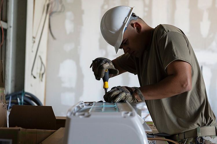
Step 2: Mount the Indoor Unit and Prepare the Wall Opening
Fix the indoor mounting plate to a suitable wall structure. Protect the hole through the wall and leave room for the refrigerant pipes, drain and wiring without squeezing insulation or bending the tubing too tightly. Seal the opening properly against weather. Check that the unit can still be removed for service after installation.
The wall opening may need a sleeve, sealant and appropriate pitch for drainage, but penetration size and fire/weather details depend on the wall assembly, code and equipment. A penetration through a rated wall needs the approved firestopping system, not generic foam alone.
Before drilling, the installer should check for concealed electrical cables, plumbing, structural members and any fire-rated wall assembly. If the planned opening would damage a critical part of the wall or cross a restricted area, change the route or use an approved detail. After routing the services, check that the exterior seal keeps out weather without blocking the condensate drain.
Step 3: Set and secure the outdoor unit
Level and fasten the outdoor unit on its designed support, with the manufacturer-required intake, discharge and service clearances. Check the pipe route and access before final anchor work; moving the unit later may require a new refrigerant layout.
For wall brackets, review substrate strength, approved fasteners, corrosion exposure and vibration isolation. For a pad, check soil, water accumulation, local snow or flood concerns and maintenance access. Confirm noise considerations rather than assuming all inverter outdoor units are quiet at every operating speed.
Step 4: Connect the mini split air conditioner line set
Use refrigerant-rated tubing and insulation of the specified sizes and lengths, then form and connect the joints using the exact model’s approved method. A line set is not interchangeable just because two products have similar nominal capacity.
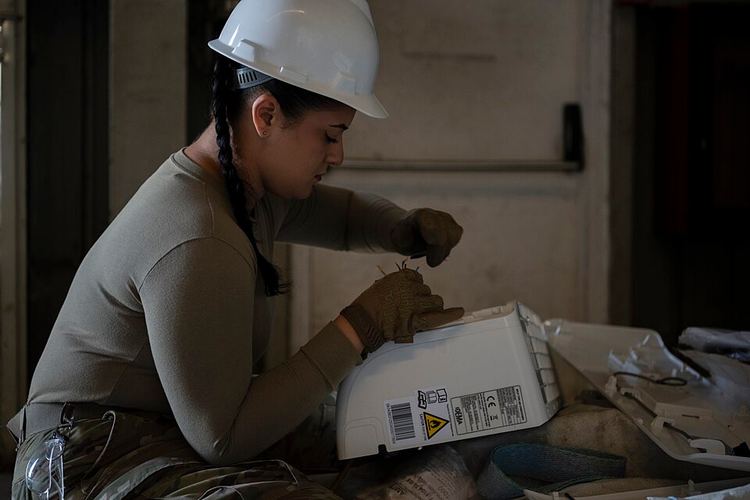
The line set is the pair of pipes that moves refrigerant between the indoor and outdoor units. A badly formed flare (the shaped pipe end at some connections), dirt or moisture inside a pipe, or torn insulation can lead to leaks, blockages or unwanted condensation. Long runs may need extra refrigerant or a different design; some models also have a minimum length. The installer must keep pipe ends clean and dry, avoid damaging edges, and follow the approved minimum bend radius so the tubing does not kink.
A line set can be within the model’s permitted length and height limits without delivering exactly the published rated output. If the manufacturer provides performance corrections for piping length, elevation or branch layout, use the values for the measured route and approved equipment combination. Compare the resulting cooling or heating output with the room’s design load. If that output is not enough, review the route or equipment selection before installation. Adding refrigerant as specified for a longer run does not, by itself, make up for a capacity shortfall.
Risk — Do not use a general article to choose connection torque (how tightly a joint is tightened), test pressure, vacuum target or the amount of refrigerant already supplied in the outdoor unit. These values depend on the exact model and refrigerant. Use only the test gas and method specified by the manufacturer; do not substitute oxygen or compressed air when dry nitrogen is required. Never release refrigerant to test a joint.
Step 5: Route and test the condensate drain
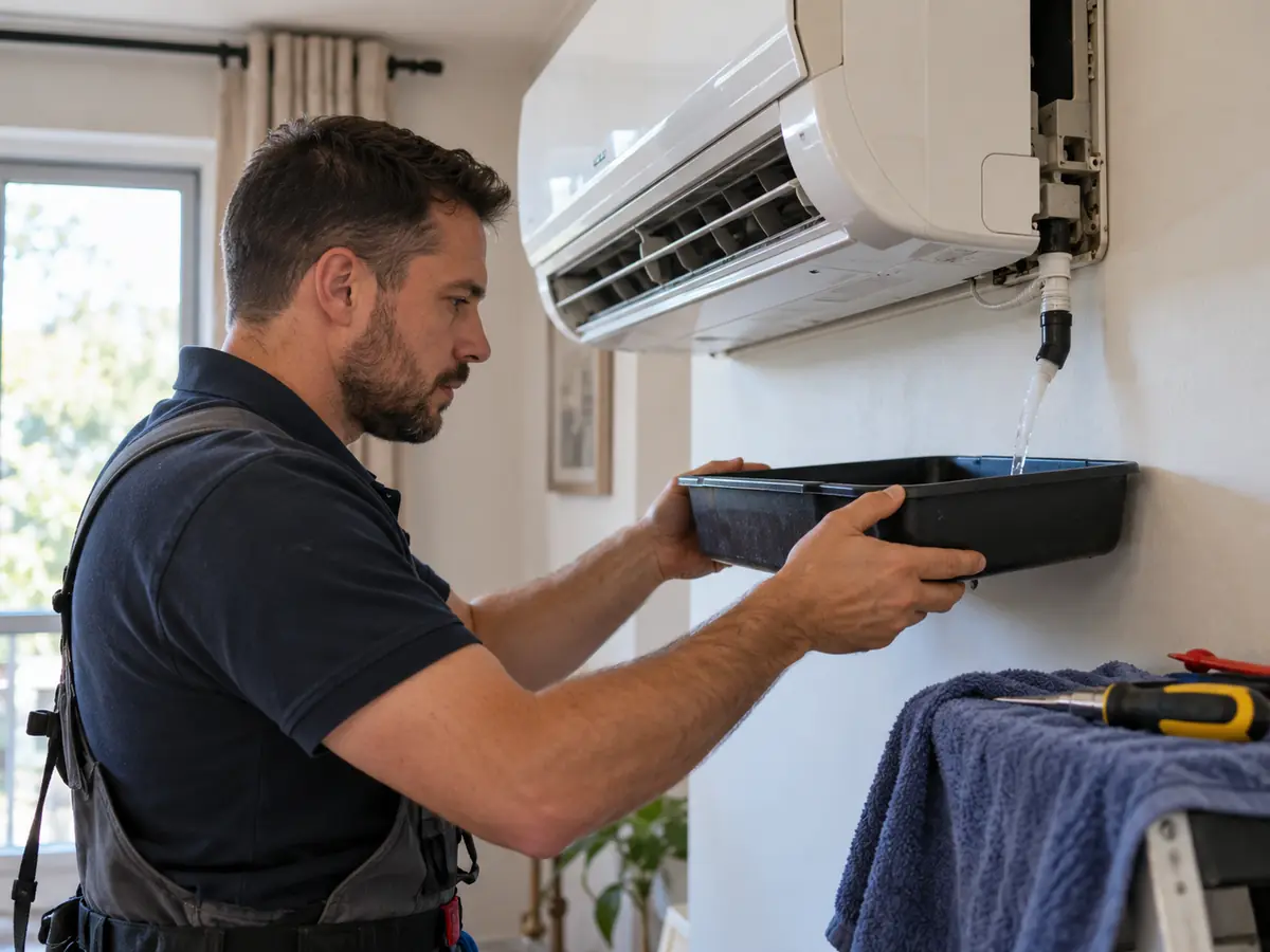
A gravity drain needs a continuous approved fall to a permitted outlet, without sags or backflow; a pumped drain needs a correctly designed lift, service access and failure protection. Confirm water actually exits before the interior is closed.

When the indoor coil cools the air, water collects and must drain away. A hose that slopes the wrong way or is blocked can make that water overflow. On some units, air pressure inside the drain area can also affect water flow. That is why the correct trap (a water-sealed drain bend), pump and overflow protection depend on the unit design: do not add a trap to every wall unit. Insulate the drain where condensation may form on its outside, and use an approved discharge location.
If gravity drainage is impossible, choose only a pump arrangement approved for that indoor unit and required lift. Have the installer test normal flow, what happens when the pump stops or loses power, and any overflow alarm or shutdown protection provided or required for the system. Confirm the discharge point is allowed locally; do not hide an untested drain connection behind a finished wall.
Step 6: Complete electrical power and communication wiring
Have a qualified installer or electrician wire the system using the diagram for the exact model. They must check the power ratings on the nameplate, the correct circuit and disconnect, grounding, protective devices, and the cable that lets the indoor and outdoor units communicate. Matching wire colors is not enough to prove a connection is safe.
Some mini splits take their main power supply at the outdoor unit and then feed the indoor unit. Others use a different design. Terminal labels, the number of conductors, communication polarity (which connection goes to which terminal), and approved cable types can all vary. Do not reuse a wiring diagram from a different model or revision. The installer must check wire ratings, breaker or fuse protection, strain relief that keeps cables from pulling loose, outdoor-rated wiring and any required inspection before startup.
If the existing supply does not match the model’s required voltage, circuit rating or protective devices, do not solve the mismatch by installing a larger breaker on unchanged wiring. A qualified electrician must assess the circuit and any needed upgrade; if that work is not feasible, reconsider the equipment or project layout before installation.
In an older building, on a long circuit run or when supply problems are suspected, checking the panel voltage with the system off may not show the voltage available at the unit during operation. Where these conditions make it relevant, a qualified electrician should assess the supply at the equipment under appropriate operating conditions and compare the result with the exact model’s permitted range and local electrical requirements. If it falls outside those limits, correct the circuit design or equipment plan. Do not bypass protection or fit a larger breaker to hide the problem.
Step 7: Test for Leaks, Remove Air and Moisture, and Check the Refrigerant
Before starting a conventional field-connected system, a qualified refrigerant technician must check that the piping does not leak, then remove air and moisture using the manufacturer’s required vacuum procedure. This step is called evacuation. The technician must also verify whether the factory-supplied refrigerant charge needs an approved adjustment. A pressure reading alone cannot prove that the circuit is dry.
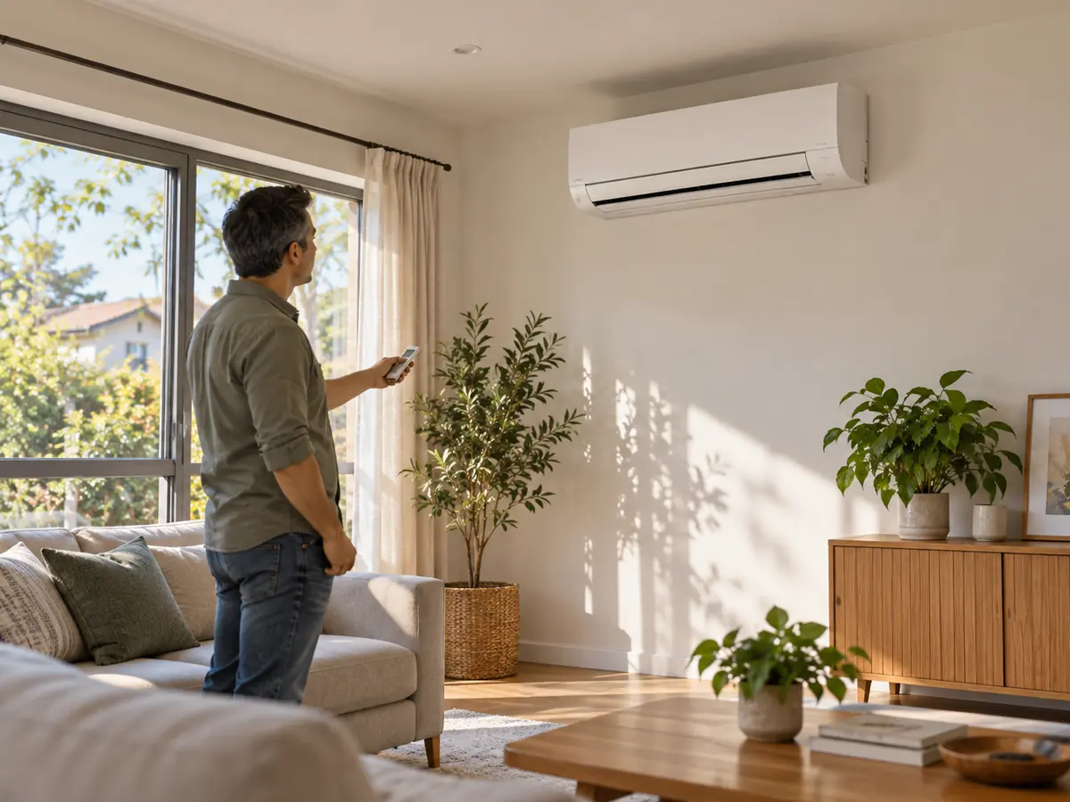
Air and moisture left in the refrigerant pipes can cause abnormal pressures, reduced efficiency and long-term damage. Technicians call trapped gases that do not condense as intended noncondensables. The proper test gas, pressure-hold criteria, vacuum method, factory-charge allowance and any added refrigerant depend on the exact equipment. Ask the technician to record the results, not just turn the system on. Factory-sealed or special precharged connection systems have their own approved instructions and legal requirements.
Ask for the relevant test method, the conditions under which the readings were taken, the manufacturer’s acceptance criteria and the actual results. If a check fails, the cause should be corrected and the check repeated before the installation is treated as verified. Record any operating test that could not be completed because of the weather or equipment conditions, along with the planned follow-up.
Step 8: Start, test and hand over the system
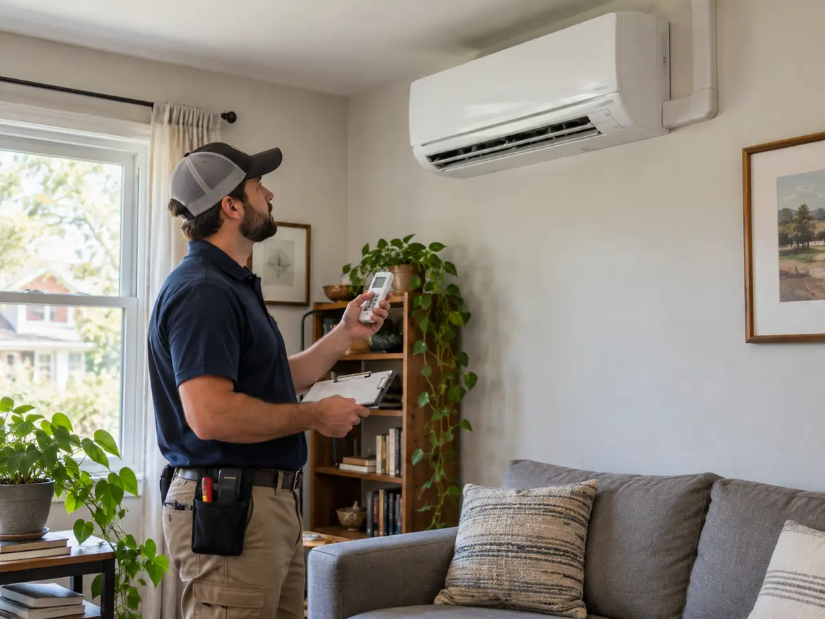
Commission the system in supported operating modes, verify airflow and temperature response, test condensate removal and safeties, and record relevant electrical and refrigerant observations against the exact manual. A working remote control and a burst of cold air do not establish correct installation.
Evaluate cooling after the manufacturer’s stabilization procedure. For reversible heat pumps, also verify heating and defrost-related settings when the ambient conditions and commissioning method permit; otherwise document what could not be tested and plan the appropriate follow-up. Explain filter access, operating modes, maintenance and warranty records to the owner.
During handover, demonstrate the supported cooling/heating modes, temperature sensing, fan settings and zone controls. Check that the controller serves the intended indoor unit and that room temperature responds where people actually sit, not only next to the indoor return grille. For multi-zone equipment, check whether the approved system allows independent mode requests or requires coordinated operation.
Before signing off, separate the equipment warranty from any installation-work coverage offered by the contractor. Ask who will respond if a drain leaks, a connection needs rework or a controller was mapped to the wrong room. Check the exact manufacturer’s warranty terms, any installer-registration conditions and the documents you need to keep. Do not assume a product warranty automatically pays for installation labor.
What should the line set, drain and wiring plan show?
Your installation plan should show where the refrigerant pipes, drain and wiring will run; how long the pipes are; and how much higher or lower one unit sits than the other. Mark protected wall openings, insulation, drain outlets, power supply and control cables. Check the model’s allowed limits before work starts, then record the actual measurements after installation.
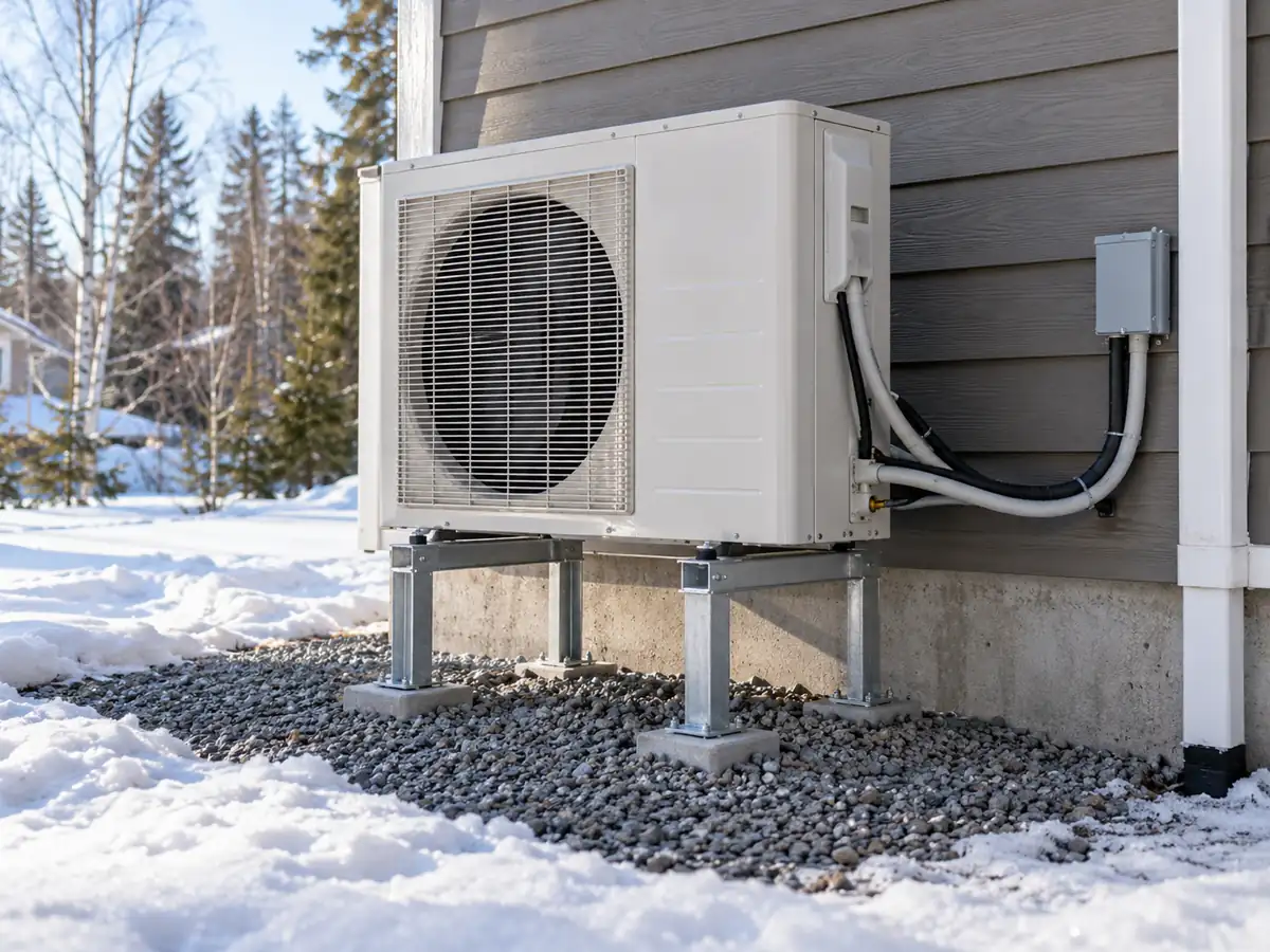
| What to include | Why it matters | What to check before the wall is closed |
|---|---|---|
| Pipe sizes and full line-set length | Affects permitted capacity, oil return and refrigerant charge | Check the exact model’s piping table against the installed route |
| Height difference between units | Too much rise or drop can make the layout invalid | Measure the levels and compare with the manual |
| Pipe insulation and outdoor protection | Helps prevent condensation, damage and unwanted heat gain | Check continuous insulation and protect exposed outdoor pipework |
| Condensate drain outlet | An uphill or blocked drain can leak indoors | Carry out the specified water-drain test |
| Power supply, disconnect and control wires | Wrong supply or wiring can damage electronics or create danger | Check the nameplate, model wiring diagram and required inspection |
| Multi-zone pipe and control mapping | A correct-looking installation can still serve the wrong room if refrigerant circuits and controls are crossed | Mark each indoor-unit ID and pipe/control circuit on the as-built plan; confirm the correct zone responds in the approved startup test. |
Verification — Keep a marked-up route drawing with the installed model identifiers, measured lengths, any changes from plan, and evidence for concealed work. On multi-zone installations, identify each indoor circuit and check that the controls and piping are assigned to the correct zone.
How Can You Tell Whether the Installation Passed Its Final Tests?
A split air conditioner is properly installed only when the installer can show the safety and operating checks, not just switch it on. Ask for electrical checks, refrigerant leak and vacuum records, any required charge verification, a working drain, clear airflow and operating readings taken under the manufacturer’s test conditions. If hot or cold weather prevented a full check, ask what still needs testing later.
| Check | What it helps confirm | What it does not prove on its own |
|---|---|---|
| Refrigerant leak and evacuation records | Required pipe-tightness and moisture-removal tests were completed | Correct room size or airflow |
| Electrical and power checks | Supply, wiring and protection were checked | Correct refrigerant charge |
| Drain water test | Water leaves through the intended outlet during the test | Drainage will never need cleaning or maintenance |
| Airflow and temperature response | The unit moves air and responds during the test | Full rated output in the hottest weather |
| Running readings or manufacturer diagnostics | Operation was checked under the recorded test conditions | Annual efficiency or heating output in extreme cold |
Ask for the final model numbers, the actual installed pipe length (often called the as-built length), test results, running measurements and instructions for cleaning filters and reading fault alarms. If the installer only shows that the room cools down, ask what else was checked. A mild-weather startup establishes operation only under the measured conditions. It does not prove available capacity on the hottest design day, moisture removal under a high-humidity load, or winter heating output during defrost. Keep the recorded test conditions, compare with the manufacturer’s method and criteria, and list any weather-dependent tests to revisit rather than treating published ratings as measured results.
What installation mistakes cause the most trouble?
The problems that cause the most trouble are poor drainage, the wrong unit size or location, leaking or incorrectly made refrigerant connections, pipes outside the allowed length, blocked outdoor airflow and wiring mistakes. A symptom can have several causes. Check the likely cause with the installer before replacing equipment or adding refrigerant.
| What you notice | Possible installation reason | What to check safely |
|---|---|---|
| Water dripping indoors | Drain slopes the wrong way, blocked hose, pump failure or condensation on uninsulated parts | Stop cooling if water may reach electrics; have the drain tested |
| Unit runs but cooling is weak | Wrong capacity, blocked airflow, wrong mode or refrigerant problem | Check clear airflow and ask for the load and startup records |
| Outdoor unit switches off or trips | Blocked discharge, power or wiring fault, or safety protection | Keep it off if unsafe; ask a qualified technician to check the fault code and supply |
| Unusual noise or shaking | Loose support, touching refrigerant pipes or a mount that amplifies vibration | Check visible support and clearances without opening live equipment |
| One room in a multi-zone system does not work | Wrong control-to-pipe assignment, shared capacity limit or system fault | Ask for zone mapping and the approved unit combination |
If a new system performs poorly, first confirm the requested mode and setpoint, unobstructed filters and airflow, and any visible fault message. Stop if there is water near electrical parts, a tripped protective device, damaged wiring, unusual vibration or a suspected refrigerant leak. A qualified technician should then compare the startup records, wiring and zone assignments, refrigerant test results and design load before changing the charge or replacing equipment.
A low-refrigerant warning is not permission to top up the system. Properly installed sealed circuits should not need routine replenishment; suspected charge loss calls for fault diagnosis and leak repair by a qualified technician. A cold supply-air reading alone also cannot rule out oversizing or poor humidity control; compare the selected model with the calculated load.
How much does split air conditioner installation cost?
In the United States, published consumer estimates put some straightforward single-zone ductless mini split installations at roughly $2,500–$6,000 including installation. This is a broad reference range, not a quote from Airproz or a budget for every home. Multi-zone equipment, difficult access, longer refrigerant pipe runs and electrical upgrades can raise the cost. Ask for an itemized local estimate.
Request a written itemized estimate, including removal of existing equipment when applicable. A straightforward wall-mounted single-zone job differs from a multi-zone retrofit, ceiling cassette or hard-to-access outdoor unit. The equipment price alone is not the total installed cost; use the table and scope check below to compare complete installations.
| What affects the price | Why the job may cost more | What to ask the installer |
|---|---|---|
| Number of rooms and indoor-unit type | More pipes, controls and access work | How many zones and which approved models are included? |
| Pipe length and routing | More material, wall openings, difficult access or approved refrigerant adjustments | What length is included, what costs extra, and what are the model limits? |
| Electrical work | A dedicated circuit or service upgrade may be needed | Which circuits, inspections and electrical costs are included? |
| Drainage, mounting and access | A pump, pad, bracket, lifting equipment or repairs may be needed | How will the units be supported and water drained? |
| Testing and warranty handover | Quotes may differ in final testing and paperwork | Which tests, permits and warranty documents are included? |
Compare written quotes only after each installer identifies the exact equipment, rooms served and full scope of work. Check who is responsible for electrical changes, permits and inspections, mounting, drainage, refrigerant piping, startup tests, cleanup and handover documents. If a quote excludes a required task, compare the total completed-project cost rather than the headline price. The $2,500–$6,000 figure above comes from a HomeGuide U.S. market reference updated in October 2025. It is not an Airproz price or a guarantee of local prices in 2026.
Frequently asked questions
How long does it take to install a split air conditioner?
Some accessible single-zone installations can be completed in one working day, but that is not a guaranteed project timeline. Extra indoor units, electrical upgrades, difficult wall openings, permits, inspections or follow-up testing can extend the schedule. Ask which safety and startup checks will be finished before handover; a fast installation is not proof of a good one.
Does a mini split air conditioner need a dedicated electrical circuit?
Many fixed mini splits need their own electrical circuit, called a dedicated branch circuit. The correct supply, wire size, breaker or fuse and disconnect depend on the exact nameplate, manual and local electrical code. Do not choose a breaker or plug based only on the unit’s BTU rating.
Can you reuse an existing mini split line set?
Sometimes, but only if the new unit manufacturer allows it. Check the old pipe sizes, condition, cleanliness, insulation, refrigerant compatibility and route against the new manual. Pipes that fit the connectors can still be unsuitable or contaminated enough to damage the new equipment.
Can a single outdoor unit serve several indoor units?
Yes, if it is an approved multi-zone system. The outdoor unit and each indoor unit must be listed as a compatible combination. Check pipe-length limits, controls, total connected capacity and how much cooling or heating the outdoor unit can supply when several rooms need it at once. You cannot automatically connect multiple indoor units to a single-zone outdoor unit.
What Makes a Split AC Installation Properly Complete?
A split air conditioner installation is not complete just because the unit turns on. The equipment must be properly sized and matched, safely mounted and connected, correctly drained, and tested against the instructions for the exact model.
Before handover, confirm that the installer has checked electrical safety, refrigerant connections, drainage and normal operation. Keep the matched model numbers, room-load and design-condition basis, measured line-set route, relevant electrical and refrigerant test records, drainage test result, control demonstration, user instructions and any weather-dependent follow-up tests. If a required result is missing, ask the qualified installer to document and complete the check before treating the job as fully verified.
Sources
- Equipment sizing: ACCA Manual J addresses residential cooling and heating loads. ACCA Manual S addresses equipment selection using the building load, design conditions and manufacturer performance data.
- Installation quality: ACCA’s HVAC Quality Installation Specification and ENERGY STAR’s HVAC Quality Installation guidance explain quality checks.
- U.S. refrigerant safety: EPA Section 608 rules and the EPA mini-split FAQ describe applicable technician-certification requirements.
- Cost reference: HomeGuide, “How Much Does a Mini Split Installation Cost?” (October 8, 2025), provides the indicative U.S. single-zone installed-price range; it is not an Airproz quotation.
- Model-specific requirements: The current manual for the exact equipment and applicable local rules govern site-specific procedures and limits.
Questions About Split Air Conditioner Equipment?
If you are reviewing a split AC system, prepare the building location, rooms to be served, heating or cooling needs, power supply and possible unit locations. These details help clarify which model information and installation conditions must be checked.
For distributor or project inquiries, also include the destination market, expected quantity, proposed model numbers, design conditions and any required technical documents. Final on-site design, licensing, permits, installation and commissioning remain the responsibility of the qualified local professionals engaged for the project.
For equipment-related questions, contact us with the details relevant to your project.