Quick answer: an air-to-water heat pump moves heat through two separate circuits. Refrigerant absorbs heat from outdoor air, the compressor raises the refrigerant’s pressure and temperature, and a refrigerant-to-water heat exchanger transfers that heat into a separate water circuit. Different HVAC compressor types use different mechanical methods to raise refrigerant pressure, but their role in the heat-pump cycle is the same: preparing the refrigerant to release heat at a higher temperature.
The compressor works on the refrigerant; it does not directly heat the building water. During normal operation, the refrigerant and heating water remain physically separate. Exact capacity, COP and water-temperature limits still need to be checked for the specific model and operating condition.
The Short Answer: Two Circuits, One Heat Exchanger
An air-to-water heat pump combines a refrigeration circuit with a hydronic, or water-based, heating circuit.
The refrigerant circuit contains the refrigerant, compressor, air-side heat exchanger and expansion device. Its job is to collect low-temperature heat from outdoor air and raise that heat to a useful temperature level.
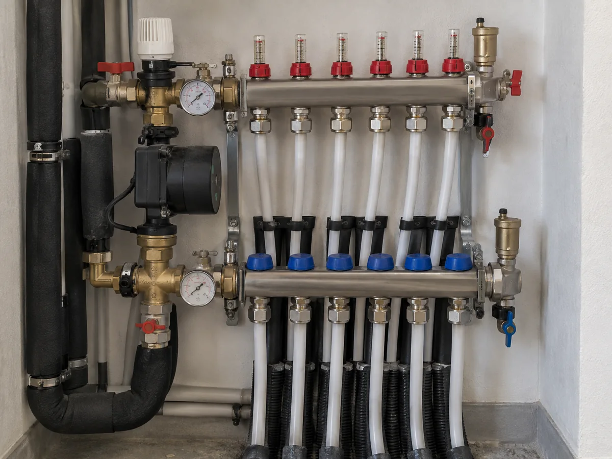
The water circuit carries heating water between the heat pump and the building. Depending on the system, that water may serve underfloor loops, radiators, fan coils or an indirect hot-water cylinder.
The two circuits meet thermally at the refrigerant-to-water heat exchanger. A brazed-plate heat exchanger is one common implementation, although the exact construction and location depend on the product design. Hot refrigerant flows on one side of the heat-transfer surface and cooler water flows on the other. Heat crosses the metal wall; the two fluids are designed to remain physically separated during normal operation.
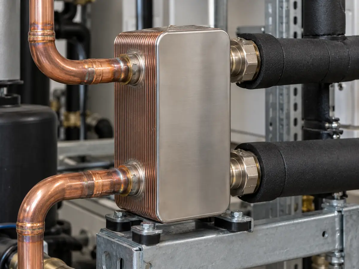
That distinction prevents one of the most common misunderstandings about air-to-water heat pumps: refrigerant is not normally pumped through the building’s radiators or underfloor loops, and the compressor is not pumping or directly heating the system water.
If you are looking at a schematic, trace the refrigerant loop until it reaches the refrigerant-to-water heat exchanger, then trace the supply and return water connections on the other side. That is the point where energy crosses from the refrigeration system into the hydronic system.
Key facts
- The refrigerant circuit and heating-water circuit stay separate during normal operation.
- Colder outdoor air and hotter required water both increase the temperature gap the heat pump must bridge.
- Maximum water temperature and minimum operating temperature are limits, not guarantees of COP or full heating capacity.
- Use the working principle to understand the system; use current model data to prove model-specific performance.
Main components and their jobs
| Component | What it does |
|---|---|
| Outdoor air-side heat exchanger | Absorbs heat from outdoor air into the refrigerant. |
| Refrigerant | Carries heat through the refrigeration circuit as its pressure and state change. |
| Compressor | Raises refrigerant pressure and temperature so heat can be released at a useful temperature. |
| Refrigerant-to-water heat exchanger | Transfers heat from the refrigerant into the separate heating-water circuit. |
| Circulation pump | Moves heating water through the hydronic system. |
| Heat emitter | Releases heat into the building through underfloor loops, radiators or fan coils. |
Step by Step: How Heat Moves from Outdoor Air into Water
The basic heating cycle has four thermodynamic functions: evaporation, compression, heat rejection into the water, and expansion. Controls may vary compressor, fan and pump speeds as load changes, but those four functions remain the core of the process.
1. Evaporation: the refrigerant absorbs heat from outdoor air
In heating mode, the outdoor air-side heat exchanger acts as the evaporator. A fan moves outdoor air across the coil while cold, low-pressure refrigerant flows through it.
Because the refrigerant is colder than the outdoor air at the heat exchanger, heat moves from the air into the refrigerant. The refrigerant evaporates as it absorbs that energy and leaves the outdoor heat exchanger as a low-pressure vapor.
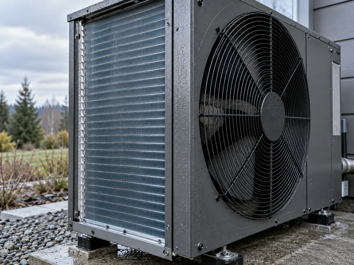
The air does not need to feel warm to a person for this to work. What matters is the temperature difference between the outdoor air and the refrigerant in the evaporator.
2. Compression: refrigerant pressure and temperature rise
The compressor draws in the low-pressure refrigerant vapor and compresses it. Compression raises both its pressure and temperature, producing hot, high-pressure refrigerant vapor.
The compressor is usually the dominant electrical load in the refrigeration circuit, but it is not the only electrical load in the complete heat-pump system. Outdoor fans, circulation pumps, controls and any auxiliary electric heater also use electricity.
The important point is what the compressor does: it prepares the refrigerant to release heat at a temperature high enough to heat the water circuit.
3. Heat transfer: the refrigerant releases heat into the water
The hot refrigerant then enters the refrigerant-to-water heat exchanger. Heating water passes through the other side.
Because the refrigerant is hotter than the water, heat moves across the heat-exchanger wall into the water. As the refrigerant gives up energy, it condenses from vapor toward liquid at high pressure. At the same time, the water leaves the heat exchanger warmer than it entered.
This is the actual transfer point between the two circuits. The compressor raises the refrigerant’s energy level; the heat exchanger passes that energy into the water.
4. Expansion: the refrigerant cools and returns to the outdoor coil
After releasing heat, the high-pressure refrigerant passes through an expansion device. Its pressure falls sharply, lowering its temperature and preparing it to absorb heat from outdoor air again.
The refrigerant returns to the outdoor heat exchanger and the cycle repeats.
While the unit is actively heating, the water circuit circulates on the other side. The refrigeration cycle and water circulation operate together rather than as two separate time-based stages.
Engineering takeaway
The compressor changes the refrigerant’s pressure and temperature; the refrigerant-to-water heat exchanger is where heat actually crosses into the water circuit. The compressor does not directly heat the system water, and one maximum water-temperature rating does not tell you the system’s real heating capacity or efficiency.
What Happens on the Water Side After Heat Transfer
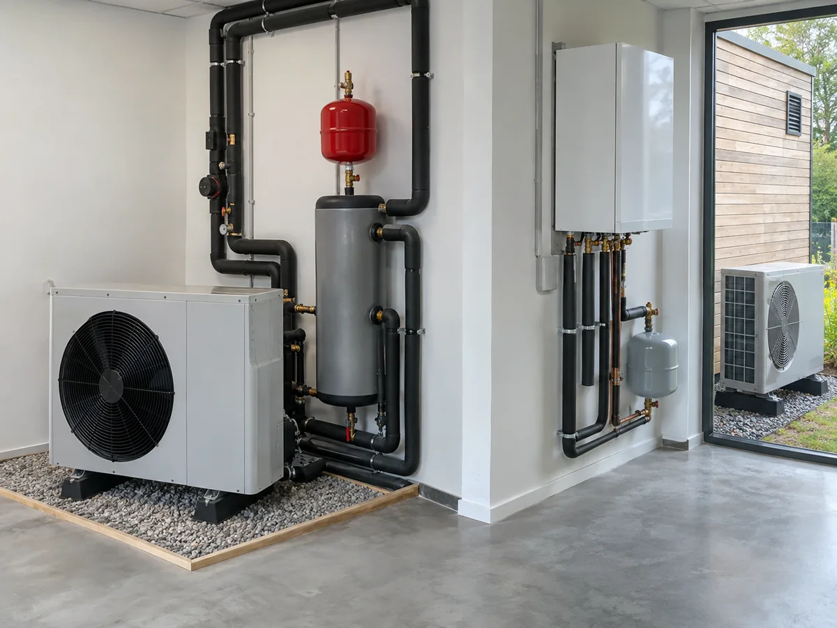
Once the water has absorbed heat in the refrigerant-to-water heat exchanger, a circulation pump moves it through the building’s hydronic system.
The supply water is the water leaving the heat pump toward the load. In heating mode, it is warmer than the return water, which comes back after releasing heat into the building or a hot-water cylinder.
The temperature difference between the water leaving the heat pump and the water returning from the building is called delta T. In simple terms, it shows how much the water cools as it gives heat to the building. There is no single correct delta T for every installation because flow rate, emitter design, controls and manufacturer requirements all affect the expected value.
Typical destinations include:
| Water-side load | What happens to the heat |
|---|---|
| Underfloor heating | Warm water circulates through floor loops and releases heat over a large surface area. |
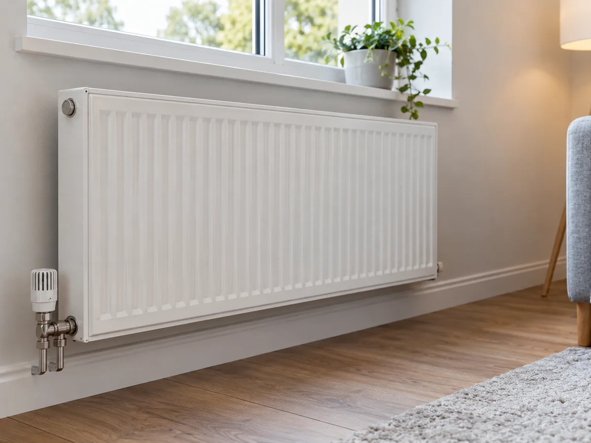
| Radiators | Water releases heat through radiator surfaces; required water temperature depends heavily on radiator sizing and building load. |
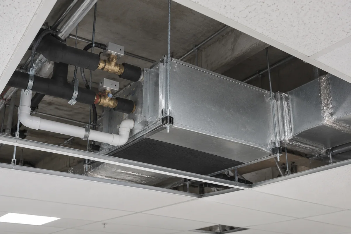
| Fan coil units | Water passes through a coil while a fan transfers heat between the coil and room air. |
| Indirect domestic hot-water cylinder | Primary heating water passes through a coil or heat exchanger that heats the stored potable water without intentionally mixing with it. |
The type and size of the heat emitter matter because they influence the water temperature the heat pump must produce. A large emitter that can meet the room load at a lower water temperature generally makes the heat pump’s job easier than a small emitter that requires much hotter water.
Domestic hot water needs one extra distinction. In a typical indirect-cylinder arrangement, the water circulating through the heat pump is primary heating water. It transfers heat through a cylinder coil or heat exchanger into the stored potable water. The heating circuit and the water delivered to taps are normally hydraulically separate.
Some systems prioritize domestic hot-water charging and temporarily reduce or pause space-heating delivery while the cylinder reheats. Others use different hydraulic arrangements. Do not assume that a system marketed for heating, cooling and hot water can deliver all three at full output at the same time; check the actual control and hydraulic design.
Why Outdoor Temperature and Water Temperature Change Performance
The basic cycle does not change when the weather gets colder or when the building asks for hotter water, but the operating difficulty does.
A useful concept is temperature lift. In simple terms, it is the temperature gap the heat pump must bridge between the outdoor heat source and the hotter water the building needs. Colder outdoor air makes the source side colder. Higher leaving-water temperature makes the load side hotter. Either change increases the lift the compressor must create.
In general:
| What changes | What it usually means |
|---|---|
| Outdoor temperature falls | The heat pump generally has to work across a larger temperature lift; efficiency can fall and available capacity can change. |
| Required water temperature rises | Compressor lift increases, so COP generally falls. |
| Outdoor air becomes cold and humid | Frost risk on the outdoor coil increases and defrost becomes more important. |
| Lower-temperature emitters can meet the building load | Required water temperature can be lower, which generally supports more favorable heat-pump efficiency. |
Why these two temperatures matter together
A particularly demanding combination is low outdoor temperature plus high required water temperature. The heat pump has to collect heat from a colder source and deliver it at a hotter temperature, so the compressor must bridge a larger temperature gap.
This generally increases compressor work, so COP tends to fall and available heating capacity may also change. That is why one headline COP or nominal-capacity value cannot describe every climate and heating system.
Same heat pump, different operating conditions
Imagine the same air-to-water heat pump serving two different heating systems. System A can meet the building load with about 35°C water, such as a well-sized low-temperature floor-heating system. System B needs about 55°C water, such as a radiator system designed around hotter water.
The heat pump has not changed; the job it has to do has changed. System B asks the compressor to lift heat to a higher water temperature. If outdoor air is also colder, that temperature gap becomes larger again. Efficiency will generally be lower, and available heating capacity may also change.
What this means: one COP or nominal-capacity number cannot describe the same heat pump in every building and climate. Compare performance at the actual outdoor and water temperatures that matter to the project.
COP, or coefficient of performance, compares heat output with electrical input at one defined operating condition. A COP of 4, for example, means about four units of heat output for each unit of electricity used under that test condition. SCOP, or seasonal coefficient of performance, is different: it estimates seasonal efficiency using a specified test method and set of operating assumptions. Neither metric should be read without its rating basis.
The same caution applies to capacity. A nominal heating-capacity value measured at one condition does not automatically equal the capacity available at the project’s winter design temperature and required leaving-water temperature.
If low-ambient performance is a major project concern, our space heating heat pump for cold climate guide explains how to compare capacity and COP at winter design temperatures instead of relying on the minimum operating temperature alone.
Likewise, an operating-range limit or maximum leaving-water temperature tells you that operation may be possible within a stated boundary; it does not by itself prove rated capacity or efficient operation at that limit.
If a project decision depends on exact capacity or efficiency, move from the generic working principle to the exact model’s performance table at the required outdoor and water temperatures.
What Changes During Defrost and Reversible Cooling
The normal heating explanation assumes that heat is moving from outdoor air into the water circuit. Two operating conditions can intentionally change that direction: defrost and reversible cooling.
Defrost: why the outdoor coil temporarily needs heat
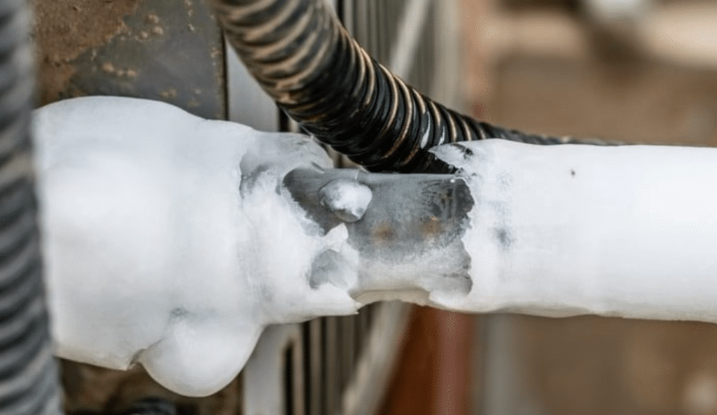
In heating mode, the outdoor heat exchanger must run cold enough to absorb heat from outdoor air. In cold, humid conditions, moisture can freeze on the coil surface. If frost keeps building, it blocks airflow and adds thermal resistance, reducing the coil’s ability to absorb heat.
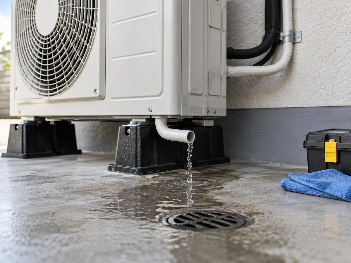
Many air-source heat pumps therefore use reverse-cycle defrost. For a short period, refrigerant flow is redirected so that the outdoor coil receives heat and melts the frost. Depending on the system design, some of the energy needed for that process can be taken from the hydronic side, so heating delivery may temporarily fall and the leaving-water temperature may dip.
The exact defrost strategy, trigger conditions and water-side requirements are model-specific. A heating-only heat pump may still use refrigerant reversing hardware for defrost, so “heating-only” does not automatically mean “no reversing valve.”
System water volume can help moderate short temperature changes during defrost, but that does not mean every installation needs a buffer tank. Buffer requirements depend on minimum flow, system water volume, zoning, emitter design, defrost strategy and the manufacturer’s hydraulic requirements.
Reversible cooling: the water-side heat exchanger changes role
A heat pump designed for reversible chilled-water operation can also move heat in the opposite direction during cooling.
Instead of releasing heat into the water circuit, the refrigerant-to-water heat exchanger absorbs heat from the water. The system then rejects that heat to outdoor air. The building receives chilled water rather than heated water.
Cooling capability should be confirmed from product documentation rather than inferred from the basic heating cycle. Chilled-water operation also changes building-side requirements: pipe insulation, emitter suitability, condensate drainage and dew-point control become important.
Monobloc vs Split: What Changes and What Does Not
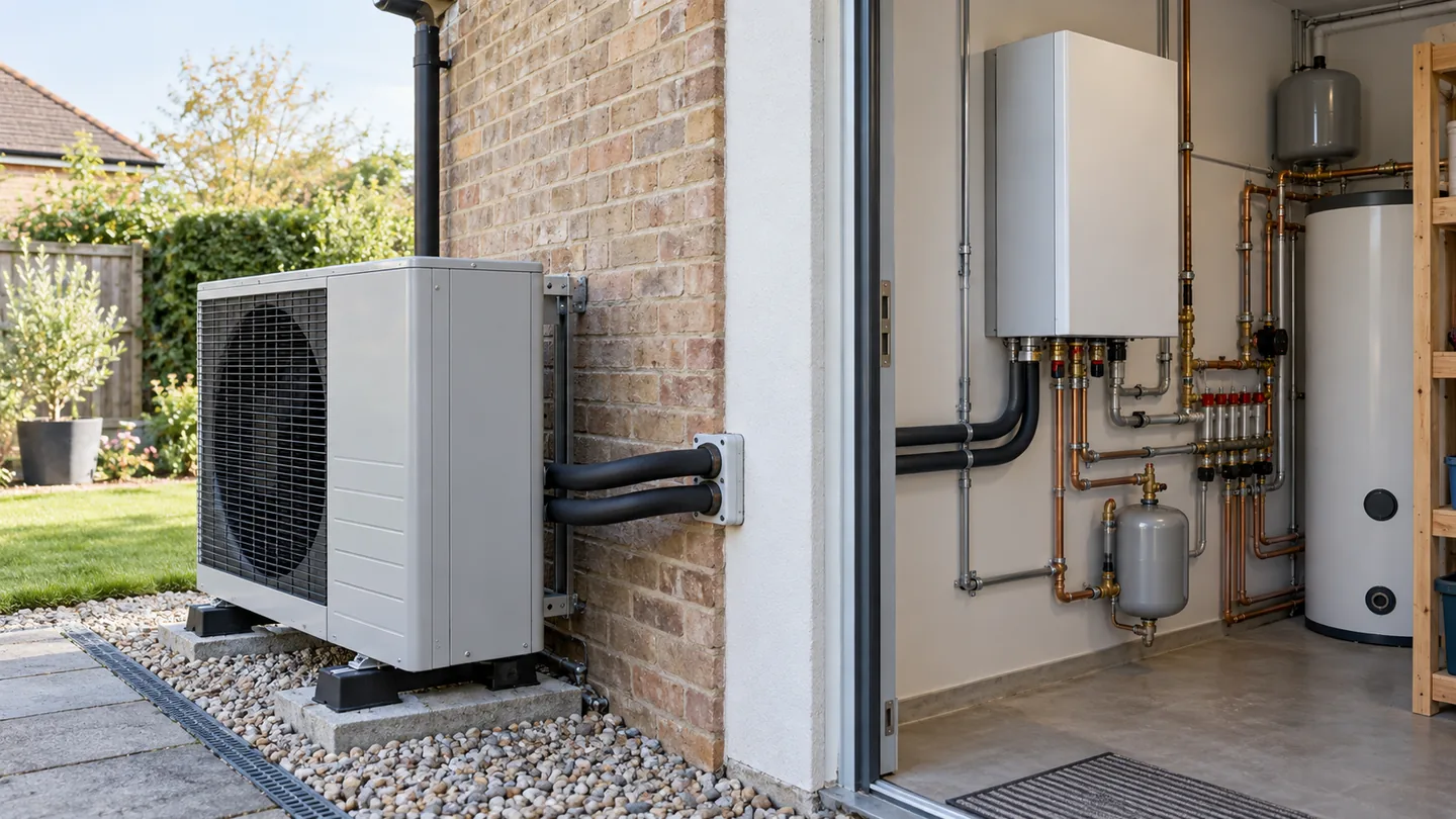
Monobloc and split air-to-water heat pumps use the same basic refrigeration-to-water heat-transfer principle. The main difference is how the equipment is packaged and which fluid crosses between outdoor and indoor equipment.
| Item | Typical monobloc arrangement | Typical refrigerant-split arrangement |
|---|---|---|
| Refrigerant circuit | Usually contained within the outdoor unit | Extends between outdoor and indoor sections |
| Connection into the building | Commonly water pipework | Commonly refrigerant pipework to an indoor hydrobox |
| Refrigerant-to-water heat exchanger | Commonly in the outdoor unit | Commonly in the indoor hydraulic section, depending on design |
| What to check during installation | Outdoor water pipework needs appropriate freeze protection | Refrigerant connection and handling requirements become part of installation |
| How to confirm the actual layout | Manufacturer hydraulic/refrigerant schematic | Manufacturer hydraulic/refrigerant schematic |
These are typical arrangements, not universal rules. Hydro-split and other architectures exist, so the product schematic is more reliable than the label alone.
Do not use the layout label as a performance shortcut.
The layout label also does not tell you that one product must have better efficiency or capacity than another. Performance depends on the actual compressor, heat exchangers, controls, refrigerant circuit, installation and operating conditions. Compare exact products at matched conditions if performance is the question.
What to Verify on a Real Heat Pump Before You Infer Performance
What this article can—and cannot—tell you
The working principle explains how heat moves. It does not prove every performance or system-design claim for a specific model.
Evidence boundary: public technical guidance such as the UK Energy Technology List and Natural Resources Canada heat-pump basics can support general system and operating principles. Exact model capacity, COP, water-temperature limits, hydraulic requirements and certification scope should come from current model-specific documentation.
What each specification can—and cannot—tell you
| Specification | What it tells you | What it does not prove | What to verify next |
|---|---|---|---|
| COP | Efficiency at one stated operating condition. | Seasonal efficiency or exact annual electricity use. | Check the outdoor temperature, leaving-water temperature and test condition behind the COP value. |
| SCOP | Seasonal efficiency under a specified test method and climate assumptions. | Your building’s exact seasonal electricity use or cost. | Check the climate assumptions, water-temperature application and rating method. |
| Heating capacity | Heat output at the stated outdoor and water conditions. | The same output at every outdoor temperature or water temperature. | Check capacity at the project’s winter design temperature and required leaving-water temperature. |
| Maximum leaving-water temperature | A stated water-temperature operating limit. | High COP or full heating capacity at that temperature. | Check both capacity and COP at the water temperature the building actually needs. |
| Operating range | The stated environmental range in which operation is permitted. | Full rated output across the entire range. | Check the model’s performance table at the actual design point, not only the minimum operating temperature. |
What to check on a datasheet
When you move from the general working principle to a specific air-to-water heat pump, verify these five items together:
- Outdoor design temperature. Use the winter condition that matters to the project, not only a mild nominal test point.
- Heating capacity at that outdoor temperature. Confirm the heat output available at the design condition.
- Required leaving-water temperature. Match the performance data to the water temperature needed by the emitters.
- COP at the same operating point. Compare efficiency at the same outdoor and water temperatures used for the capacity check.
- Water-flow and hydraulic requirements. Check minimum flow, required system water volume and any model-specific hydraulic requirements.
Do not select from one headline number alone. Maximum water temperature, nominal capacity or one COP value cannot prove performance at every project condition.

Three performance shortcuts to avoid
Misunderstanding: “A higher maximum water temperature means a better heat pump.”
Why this is wrong: Maximum leaving-water temperature is an operating limit. It does not prove high COP or full heating capacity at that temperature.
Check instead: Compare both heating capacity and COP at the leaving-water temperature the building actually requires.
Misunderstanding: “Monobloc is always more efficient than split.”
Why this is wrong: Monobloc and split describe system architecture, not a guaranteed efficiency level.
Check instead: Compare the exact models at the same outdoor temperature, leaving-water temperature and rating condition.
Misunderstanding: “If the heat pump can run in very cold weather, it must still deliver full rated capacity.”
Why this is wrong: Minimum operating temperature and available heating capacity are different specifications.
Check instead: Use the model’s heating-capacity table at the project’s winter design temperature and required leaving-water temperature.
A good rule is simple: use the operating principle to understand the system, and use current model documentation to prove model-specific performance.
FAQ
Do refrigerant and heating water mix?
No, not during normal operation. Heat crosses the wall of the refrigerant-to-water heat exchanger, while the refrigerant and heating water stay in separate circuits. A leak or internal heat-exchanger failure is an abnormal condition and requires service.
Does an air-to-water heat pump work in cold weather?
Yes, but its available heating capacity and efficiency can change as outdoor temperature falls. Required water temperature, product design and defrost also matter. Check the exact model’s performance data at the project’s winter design condition.
Why does higher water temperature reduce COP?
Because the heat pump has to bridge a larger temperature gap. The compressor generally needs more work to deliver hotter water, so COP tends to fall. The exact change depends on the heat pump and operating point.
Can an air-to-water heat pump provide cooling?
Yes, if the system is designed for reversible chilled-water operation. The heat pump must support cooling, and the building-side pipework and emitters must also be suitable for chilled water and condensation control.
Does every air-to-water heat pump need a buffer tank?
No. Buffer-tank requirements depend on minimum flow, required system water volume, hydraulic layout, zoning, heat emitters, defrost strategy and the manufacturer’s instructions.
What happens during defrost?
The heat pump temporarily sends heat to the outdoor coil so frost can melt. Many air-source heat pumps do this by reversing the refrigeration cycle for a short period, which can temporarily reduce heating output. The exact sequence varies by product.
Can the same system heat rooms and domestic hot water?
Yes, many air-to-water systems can heat rooms and charge an indirect domestic hot-water cylinder. How they switch or share capacity between those loads depends on the hydraulic and control design, so simultaneous full-output operation should not be assumed.
Related HVAC guides by next task
- Need to read the system drawing? Heat Pump Schematic Diagram: How to Read Piping, Wiring & System Drawings helps you trace the refrigeration, water and control paths.
- Planning the installation? Air Source Heat Pump Installation Guide covers installation conditions that can affect real system performance.
- Comparing heating-system options? Air-to-Water Heat Pump vs Boiler for Radiant Floor Heating compares a heat pump with a boiler in a hydronic heating application.
For a real project, the generic working principle stops where model-specific performance begins. If you are checking an Airproz air-to-water heat pump, use the current model performance table, hydraulic requirements and applicable documentation at the project’s actual design conditions before using family-level specifications for selection.