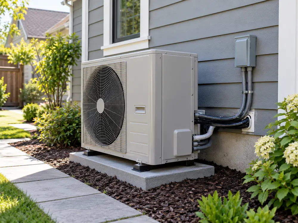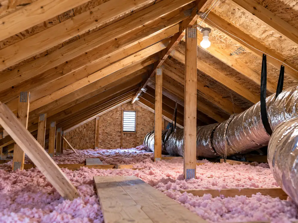
A fan coil unit (FCU) is an indoor HVAC terminal that uses a fan and heat-transfer coil to heat or cool a room or zone. A hydronic FCU circulates chilled or hot water through its coil; a direct-expansion (DX) fan coil uses refrigerant. The unit usually recirculates room air, so outdoor ventilation must be planned as part of the wider building system. For a real project, choose the FCU by its output at your design conditions, airflow, static pressure, sound, piping and service space—not floor area alone.
Fan Coil Unit at a Glance
First decide how the building supplies heating and cooling. Then check whether different rooms need opposite modes, where the unit and outlets fit, and whether its coil and fan meet the real room loads. Use the guide below to follow the decision that matters to your project.
| Question | Practical answer |
|---|---|
| What does FCU mean in HVAC? | Fan Coil Unit, a room- or zone-side heating/cooling terminal. |
| What makes it work? | A fan moves air; a water or refrigerant coil transfers heat. |
| Is every FCU a chilled-water unit? | No. Both hydronic and refrigerant-based indoor fan coils exist. |
| Can it use ducts? | Yes. Both direct-discharge and ducted layouts exist. |
| Can it supply fresh air? | Some designs accept outdoor air; many mainly recirculate air. Check the separate ventilation plan. |
| Can it heat and cool? | Yes, when the coil, piping, plant and controls support the required modes. |
| How do I choose one? | Match total and sensible duty at design conditions, airflow at required ESP, heating duty, noise, controls and maintenance access. |
| Start here if… | Go to | What to decide |
|---|---|---|
| You are new to FCUs | How the unit works | Follow room air, the coil circuit and condensate drainage. |
| Some rooms need heat while others need cooling | 2-pipe or 4-pipe | Check the available water circuits and mode controls. |
| You have shallow ceilings or several air outlets | Unit types and mounting | Check clearance, discharge layout and duct resistance. |
| You are comparing FCU offers | Sizing and selection | Compare actual cooling duty, airflow at ESP and sound at the same conditions. |
| Equipment will be installed or handed over | Installation and checks | Measure performance against the approved schedule. |
An FCU heats or cools the air in a room or zone. In a hydronic system, a chiller, boiler or suitable heat pump supplies the coil with chilled or hot water. A direct-expansion (DX) indoor fan coil works with matched refrigerant equipment. A separate air-handling unit (AHU) or dedicated outdoor-air system (DOAS) can supply treated outdoor ventilation air.
What Is a Fan Coil Unit in HVAC?
An FCU is a factory-built terminal that conditions air near the occupied space. Most include a fan or blower, one or more heat-transfer coils, a filter or upstream filter provision, and a thermostat or controller. Cooling versions also need a condensate pan and drain wherever the coil removes moisture.
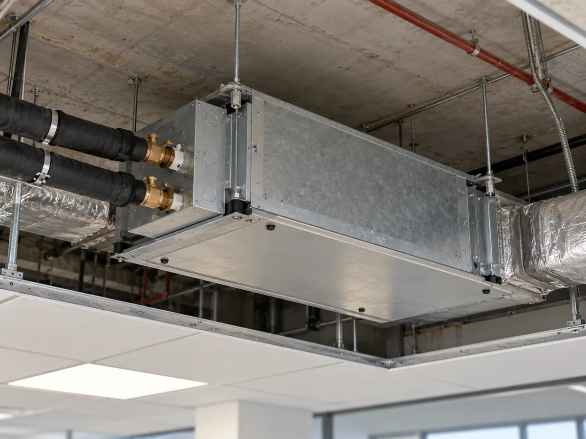
The fan moves air through the cabinet. The coil changes the air temperature by exchanging heat with chilled water, hot water or refrigerant. The conditioned air leaves the unit directly or through nearby ducts. A ceiling-concealed hydronic FCU in a hotel room and a refrigerant indoor fan coil connected to an outdoor unit can share the same broad name, yet have very different connections and selection data.
What parts are inside an FCU?
| Part | What it does | What to check on site |
|---|---|---|
| Fan and motor | Move air through the terminal and outlets | Actual airflow, speed range, vibration and access |
| Cooling/heating coil | Transfer heat between air and water or refrigerant | Coil type, design temperatures and rated capacity |
| Filter or filter frame | Catch particles and protect internal surfaces | Filter fit, pressure drop and removal space |
| Control valve or refrigerant device | Regulate coil duty with the wider system | Compatibility with plant and control sequence |
| Thermostat/controller | Respond to zone temperature and selected mode | Fan, valve, building management system (BMS) and changeover logic |
| Drain pan and drain | Remove condensate from cooling operation | Slope, trap/pump where required and cleanout access |
FCUs commonly use draw-through or blow-through airflow. In a draw-through design, the fan pulls air through the coil; in a blow-through design, the fan pushes air through it. ASHRAE’s 2024 HVAC Systems and Equipment handbook describes both arrangements.
The FCU’s finned coil is an air-to-fluid heat exchanger. For a closer look at how finned coils compare with other equipment, see our guide to types of HVAC heat exchangers.
How Does a Fan Coil Unit Work?
Room air enters the FCU, moves across a coil, and returns warmer or cooler. At the same time, water or refrigerant carries the heat to or from equipment elsewhere in the HVAC system.
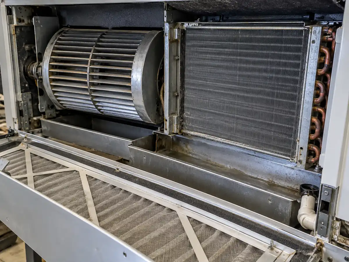
- Air returns from the room. It enters through a return grille, cabinet inlet or short return duct, usually passing a filter.
- The fan establishes airflow. A controller may select or vary fan speed to match room demand.
- The coil transfers heat. Chilled water or evaporating refrigerant removes heat during cooling; hot water or a suitable refrigerant heating cycle supplies heat during heating.
- The unit supplies conditioned air. Air leaves through the front grille, ceiling outlets or connected ducts.
- Controls adjust the output. Hydronic valves, fan speed and the central plant coordinate to meet the temperature setpoint. If the cooling coil is below the incoming air’s dew point, water condenses and must drain away.
Three paths inside an FCU: air, water and condensate
Trace the air, water and condensate paths separately. The fan moves room air across the coil fins, while chilled or hot water travels through the sealed coil tubes. Heat passes through the metal between the water and the air. The fan may sit before or after the coil, depending on the model.
Room-air path
Room return air → filter → fan and coil sections (order depends on model) → conditioned supply air → room
Hydronic water path
Chilled- or hot-water supply → inside coil tubes → water return → central water system
Condensate path (when cooling removes moisture)
Moisture on cold coil → drain pan → correctly trapped or pumped drain where required → approved disposal point
On a direct-expansion (DX) indoor fan coil, refrigerant follows the matched refrigeration system instead of a hydronic water loop. Water, refrigerant and room air stay in their own paths.
Why can two FCUs with the same nominal kW perform differently?
Cooling and heating output depends on more than cabinet size. Coil output changes with entering-air temperature and humidity, chilled-water inlet temperature and flow, airflow, coil design and fan speed. Duct resistance can reduce actual airflow; warmer chilled water may reduce available cooling. The correct comparison is delivered capacity at the same operating conditions, not the largest number printed on the cover of two catalogues.
What Types of Fan Coil Units Are Available?
Use three different classification questions: What flows in the coil? Where is the unit mounted? How is air delivered? These are independent choices. For example, one unit can be hydronic, horizontal and ducted at the same time.
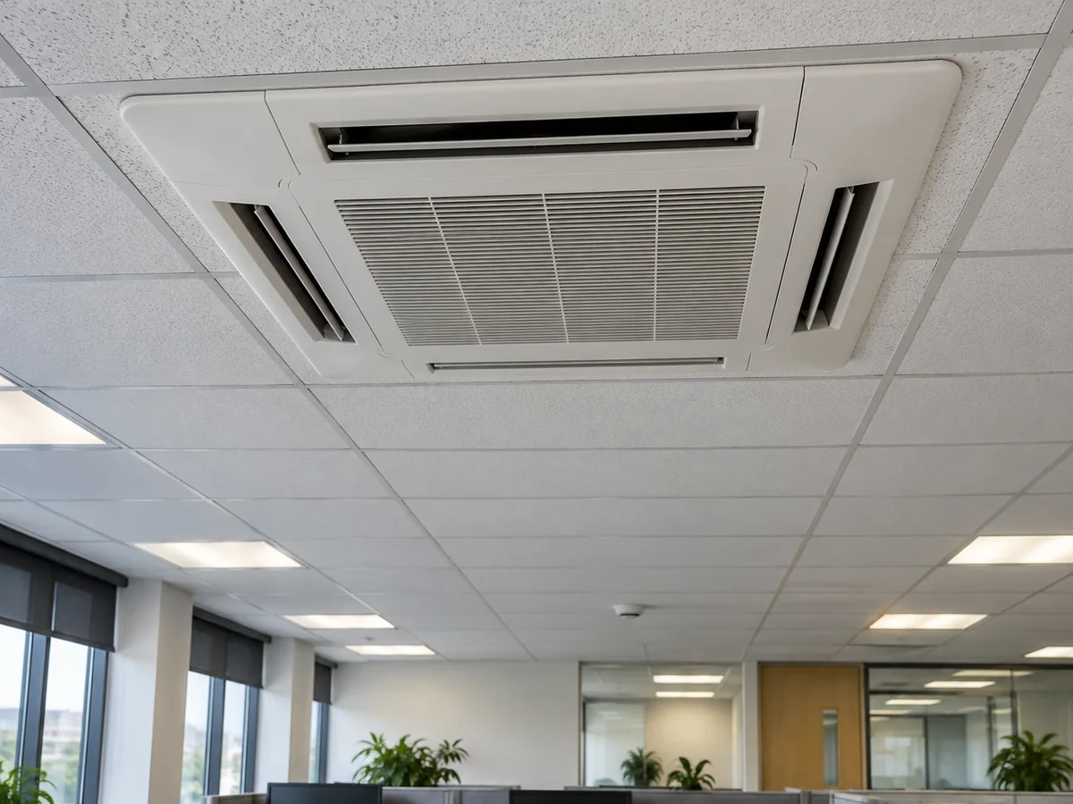
| Classification | Options | Typical deciding condition |
|---|---|---|
| Coil medium | Hydronic (chilled/hot water); DX refrigerant | Existing plant and pipe/refrigerant network |
| Mounting | Horizontal concealed; vertical cabinet/stack; ceiling cassette | Ceiling void, room layout, risers and service access |
| Air delivery | Direct-discharge/nonducted; ducted | Number/location of outlets and fan static-pressure capability |
| Heating/cooling water arrangement | 2-pipe; 4-pipe hydronic | Seasonal changeover versus different zones needing opposite modes |
Hydronic fan coil unit
A hydronic FCU connects to building water pipes. In cooling mode it receives chilled water from a chiller or another suitable water source. For heating, the system supplies hot water from a boiler or heat pump, or uses a separate heating circuit. Use a hydronic FCU when a suitable water-side plant and piping layout are already planned or available. Confirm the design entering-water temperature, water flow, available pressure and valve arrangement before selecting a model.
When the project uses a hydronic system, an air-to-water heat pump can supply the heating or cooling water. Explore the Airproz air-to-water heat pump range as one example of upstream equipment, then match the FCU coil to the chosen system’s water temperatures and flow.
Direct-expansion (DX) fan coil unit
A DX fan coil uses refrigerant in the indoor heat exchanger and operates with compatible outdoor refrigeration equipment. Select it using the manufacturer’s matched indoor/outdoor capacity data, refrigerant piping limits and control requirements. A hydronic FCU instead uses design water temperatures, water flow and water-coil selection data.
DX equipment is part of a matched refrigerant system. If you are choosing the overall system layout, compare the types of AC systems before selecting the indoor terminal configuration.
Ducted, cassette, horizontal and vertical FCUs
Start with the building space and how air must reach people. For a ducted FCU, compare its fan curve at the required external static pressure (ESP), which is the resistance from connected ducts and grilles. For a cassette or exposed FCU, check its air-discharge pattern, operating sound and service clearance.
| Building condition | Initial FCU direction | Confirm before selecting |
|---|---|---|
| Several nearby supply grilles | Concealed ducted horizontal FCU | Space above the ceiling, duct routing and fan airflow at design ESP. |
| Open office or room with local ceiling distribution | Ceiling cassette FCU | Throw/distribution pattern, noise, drain and access space. |
| Limited ceiling void or repeated perimeter rooms | Exposed vertical cabinet or stack FCU | Floor/wall position, riser connections, clearance and service access. |
| Any option requiring a quiet occupied room | Compare all feasible forms at the operating fan speed | Sound data at required duty, not only on the lowest fan setting. |
2-Pipe vs 4-Pipe Fan Coil Unit: Which Should You Choose?
Choose a 2-pipe hydronic FCU when zones can follow a common heating/cooling changeover. Choose a 4-pipe arrangement when parts of the building routinely need heating and cooling at the same time—and the plant and controls can supply both.
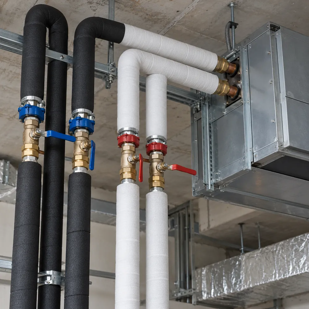
| Design point | 2-pipe hydronic | 4-pipe hydronic |
|---|---|---|
| Pipe connections at terminal | One water supply and one return | Separate supply/return pairs for heating and cooling |
| Typical operating logic | Circuit provides either chilled or hot water at a time | Separate hot- and chilled-water circuits available |
| Mixed heating/cooling demand across zones | Limited by common changeover | Can support mixed demands with suitable plant and controls |
| Installation | Usually fewer pipes and valve components | More piping, controls, connections and commissioning |
| Early project fit | Building with predictable seasonal mode | Hotel/office with opposing perimeter and core loads |
A thermostat does not create a second water temperature. A room can request cooling, but a two-pipe coil cannot cool while its shared water loop supplies hot water. A four-pipe arrangement can respond to different zones at the same time only when both water systems, valves and control logic are provided.
| Situation | Two-pipe response | Four-pipe option | Confirm |
|---|---|---|---|
| Building normally follows one season mode | Can work with a shared heat/cool changeover | Often unnecessary for this need | Who selects changeover and how the thermostat knows the current water mode. |
| Sunny and shaded rooms need opposite modes | Shared loop cannot supply two temperatures at once | Separate coils can serve different room calls | Both hot and chilled water are truly available at the same time. |
| Each room has its own thermostat | Independent setpoint, but mode remains limited by the loop | Independent zone call may select the proper coil | Valve wiring, sensor inputs and supervisory control sequence. |
| Room reaches setpoint or changes demand | Valves/fan respond within the enabled mode | Avoid heating and cooling valves fighting in one room | Deadband, fan behavior and valve interlocks at commissioning. |
For example, a sunny office zone may need cooling while a north-facing room needs heating. A common-changeover two-pipe loop cannot supply both water temperatures at once. Separate hot- and chilled-water circuits can serve the two zones if their coils, valves and central equipment are designed accordingly. In a simpler building with one seasonal mode, four pipes may add cost and maintenance without a matching operating benefit.
In a four-pipe system, the zone controller should sequence the heating and cooling valves so they do not run against each other. Set and test the temperature deadband and the switching logic during commissioning. The CIBSE fan-coil design module explains this type of control.
Where Are Fan Coil Units Most Useful?
FCUs are a practical choice for rooms with separate loads and schedules, especially where distributing heating/cooling energy through pipes or refrigerant lines is more convenient than relying only on large central ducts.
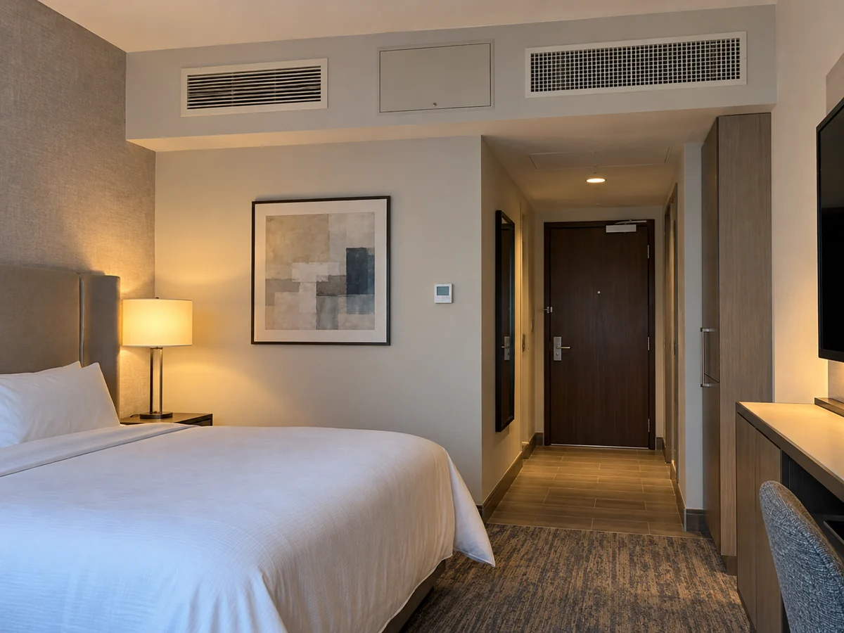
| Setting | Why a fan coil may fit | The main check before choosing |
|---|---|---|
| Hotel guestrooms | Individual room setpoints and repeated room layout | Quiet operation, service access without disturbing guests, outdoor air and drainage |
| Apartments | Zone control within flats or individual rooms | Metering, water/refrigerant distribution, maintenance ownership |
| Offices | Perimeter and interior zones with changing occupancy/load | 2-pipe vs 4-pipe, fresh-air strategy, ceiling depth, controls |
| Retrofit floors | Local terminals where major duct routes are difficult | Existing plant capacity, piping, acoustic and fire-compartment constraints |
| Clinic or special-use space | Local temperature adjustment | Facility-specific ventilation, filtration and infection-control needs may require a different system |
How building conditions change the FCU choice
Hotel-room example (illustrative): Many rooms need separate temperature settings, while a central outdoor-air system may serve the corridor and guestrooms. Compare two-pipe seasonal changeover with four-pipe room flexibility only after checking whether the building actually needs opposite heating and cooling modes at the same time. Every room also needs a workable filter and drain service route.
Office-floor retrofit (illustrative): A shallow ceiling may rule out some concealed units. If several nearby grilles are needed, confirm both the cabinet height and airflow at the estimated duct static pressure. If a sunny perimeter needs cooling while shaded rooms need heat, review the water distribution and controls before choosing a 2-pipe terminal.
What changes the installed cost?
The FCU cabinet price is only part of the project cost. Compare pipe and valve work, controls, ductwork and grilles, ceiling access, condensate pumps where needed, electrical work, testing and future filter cleaning. A less expensive cabinet can become the more expensive installed option when it needs new risers, difficult drainage or extra ceiling work.
- New pipes or four-pipe conversion: Ask for the full valve, balancing and distribution scope.
- Ducted or concealed mounting: Include access panels, acoustics, fan capability and ceiling repairs.
- Multiple rooms: Include filter/drain access time, controls integration and commissioning for each terminal.
For long distribution ducts, central filtration, high outdoor-air volumes or centralized humidity control, use an AHU or DOAS for those tasks. FCUs can still heat or cool individual rooms alongside the central air system.
Does an FCU Bring in Fresh Air?
Not automatically. A typical FCU can recirculate room air and maintain room temperature while outdoor ventilation air is supplied by a different system. Some models have an outdoor-air inlet or mixing arrangement, but the actual outdoor-air quantity still has to be designed and measured.
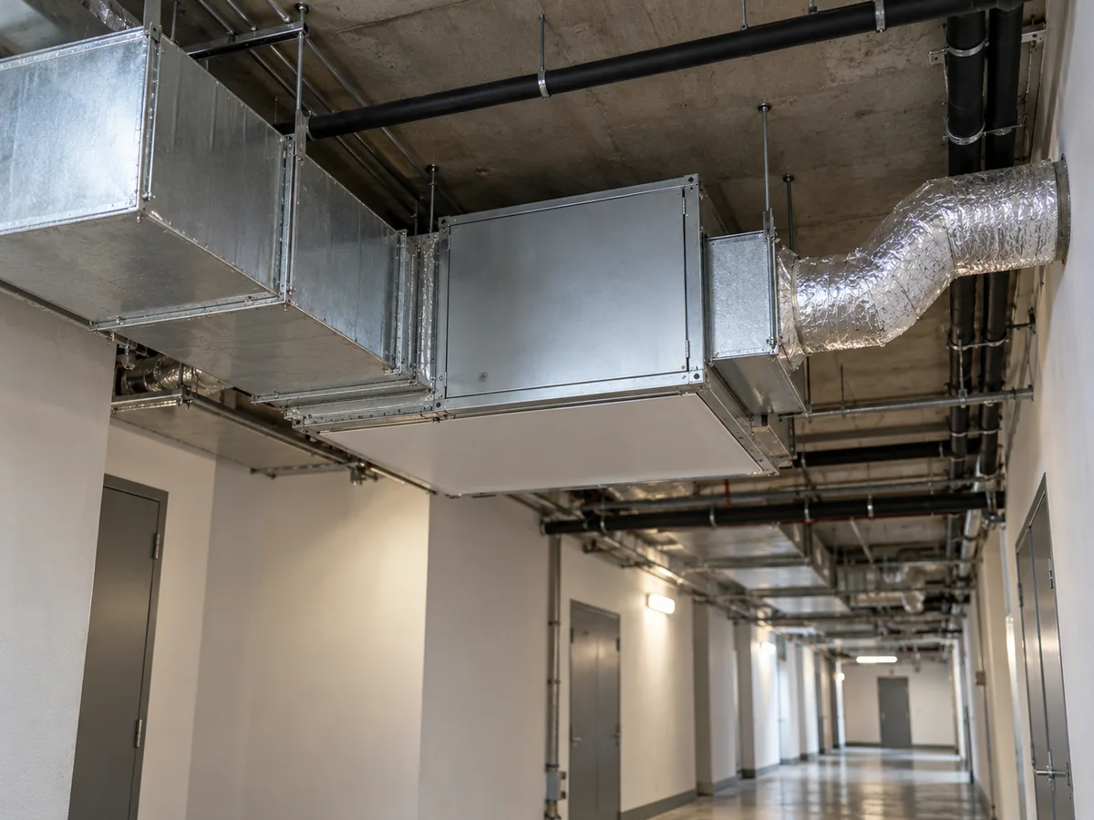
| Room air task | Who may handle it | What to verify |
|---|---|---|
| Recirculate and heat/cool room air | Local FCU | Airflow and coil performance at room design conditions. |
| Deliver the required outdoor ventilation | Central AHU, dedicated outdoor-air system (DOAS), or a designed outdoor-air connection | The actual fresh-air path and room outdoor-air quantity; a supply grille alone is not proof. |
| Control moisture from people and outdoor air | DOAS/AHU and/or FCU cooling coil as specified | Which coil removes the latent (moisture) load, its entering conditions and condensate route. |
Follow the outdoor-air route on the ventilation drawings: outdoor intake → ventilation AHU or DOAS → room or FCU mixing connection. Compare the designed outdoor-air rate with the air actually delivered, and identify where humidity is controlled. For commercial spaces, use the applicable local ventilation requirements and adopted edition of ASHRAE 62.1 where relevant. The room thermostat controls temperature; ventilation airflow is evaluated separately.
If outdoor air mixes with the returning air before the coil, the coil sees different inlet temperature and moisture conditions. That can change the total cooling load and condensate rate, so the air-mixing arrangement belongs in the selection data rather than being added after the model is chosen.
How Do You Size and Select a Fan Coil Unit?
Begin with the room’s design load, then select a model that meets both cooling and heating duty at the real air/water or refrigerant conditions. Check that the fan delivers the required airflow at the calculated external static pressure, with acceptable sound and maintenance access. Floor area by itself is an early screening clue, not a final sizing method.
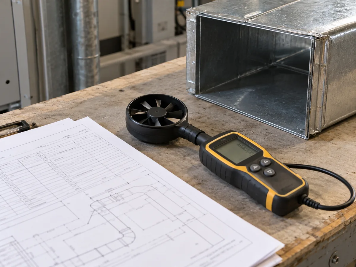
Compare every shortlisted unit at the same project operating point. Use the room-load calculation, central-plant conditions and duct layout to request manufacturer selections for total and sensible capacity, airflow at the required ESP and sound at the working fan speed.
| Project input | Manufacturer evidence to request | Decision it supports |
|---|---|---|
| Total and sensible cooling loads | Selected total and sensible duty at design entering-air temperature and humidity | Enough cooling for both temperature and moisture-related loads. |
| Chilled/hot water temperatures and target flow | Capacity at that water condition plus coil pressure drop | Match to plant and circulating pump. |
| Required supply airflow and external static pressure (ESP) | Fan performance curve at selected speed and filter configuration | Enough delivered room air after duct resistance. |
| Heating load and availability of heat source | Heating capacity and suitable coil/piping mode | Confirm winter performance and two-/four-pipe compatibility. |
| Noise and electrical supply | Sound data at duty speed and motor electrical input | Occupant comfort and site electrical compatibility. |
| Mounting, drainage and controls | Dimension/clearance drawing, trap/pump guidance and control connection diagram | Practical installation and maintenance access. |
AHRI’s Room Fan-Coils program publishes defined rating categories for total and sensible cooling and power input. Confirm the scope of the rating program for the proposed unit; a published standard rating and the project-specific duty are different pieces of information.
For a DX option, use the matched refrigerant-system selection data rather than the hydronic water-temperature and flow rows.
Step 1: Get the room cooling and heating loads
Use a project heat-load calculation that includes envelope, solar gain, people, equipment, occupancy, and ventilation. For cooling, distinguish total capacity (sensible plus latent heat removal) from sensible capacity (temperature reduction). In humid conditions, a nominal 5 kW total FCU may provide substantially less than 5 kW of sensible cooling. The chosen unit must cover each relevant load component at the specified design conditions.
Step 2: Match the coil rating conditions
For a water-based FCU, write down entering/leaving water temperatures or the design inlet temperature and flow, the entering-air dry-bulb/wet-bulb conditions, coil rows or configuration and fan speed. For DX equipment, use the approved matched-system performance table. When a brochure uses rating temperatures different from the site, use the manufacturer’s correction table or selection software to calculate duty at the project design conditions.
Dry-bulb temperature is the ordinary air-temperature reading. Wet-bulb temperature also reflects moisture in the air. Both can affect a cooling-coil rating; check the same entering-air condition for each shortlisted unit.
For a real example of upstream equipment data, the R32 monobloc heat pump performance table lists heating and cooling ratings and water flow at stated test conditions. These are heat-pump ratings; select the FCU coil separately for the project water temperatures, flow and room-air conditions.
Step 3: Check duct airflow and static pressure together
Record required room airflow and, for a ducted installation, calculated ESP from ducts, elbows, grilles and filters. Compare it with the selected FCU fan curve at the proposed operating speed. A model that lists enough free-air flow may deliver too little air once the real duct system is connected. For nonducted models, check discharge pattern and the occupied-zone draft/noise constraints instead.
Step 4: Check water flow, temperature change and balancing
For a hydronic system, an approximate water-side heat transfer calculation is:
Heat transferred (kW) ≈ 4.18 × water flow (L/s) × water temperature change (°C).
The factor 4.18 uses the specific heat and approximate density of liquid water near normal HVAC temperatures. Use this water-side estimate to check the proposed flow rate, then compare the selected coil’s capacity and pressure drop at the same design conditions using manufacturer data.
For example, a hypothetical 5.0 kW water-side duty with a 5°C design water temperature rise needs about 0.239 L/s (0.86 m³/h) of water flow. If the design water temperature change becomes 6°C at the same duty, the estimated flow drops to about 0.199 L/s (0.72 m³/h). This shows how the assumed water temperature change affects the required flow.
Step 5: Check noise, condensate, electrical and controls
Compare sound data at the fan speed required to deliver the design airflow. Confirm fan/motor supply, control voltage, BMS compatibility, filter-removal space, valve and drain access, and a workable gravity drain or approved pump arrangement. Reject a candidate if its installation space lacks safe condensate drainage or access to the filter, drain, valves and motor, even when its rated duty meets the load.
Total cooling covers both lower air temperature and moisture removal. Sensible cooling is only the temperature-changing part. If a unit meets the total load but not the sensible load, the room may still remain too warm. If the ventilation design already handles part of the moisture load, include that split in the room load calculation instead of assigning the same load twice.
Worked selection example: one office zone
Suppose a hypothetical office has a calculated peak total cooling load of 4.8 kW, including 3.7 kW sensible, and needs 400 m³/h airflow at 60 Pa ESP. The building provides chilled water at its specified design conditions. Two catalogue options are on the shortlist:
| Check | Candidate A | Candidate B |
|---|---|---|
| Nominal advertised cooling | 5.5 kW | 5.3 kW |
| Total cooling at project conditions (illustrative selection result) | 4.5 kW | 5.0 kW |
| Sensible cooling at project conditions (illustrative) | 3.6 kW | 3.9 kW |
| Airflow available at 60 Pa (illustrative) | 370 m³/h | 425 m³/h |
| Early result | Reject: misses all three needs | Continue checking sound, drainage, flow and fit |
In this illustrative comparison, Candidate B meets all three assumed minimums: 4.8 kW total, 3.7 kW sensible and 400 m³/h at 60 Pa. Candidate A falls below each requirement. These are teaching inputs, not published model ratings. For a real shortlist, compare each model’s coil duty, fan curve, operating sound, required heating capacity and drainage/installation drawings at the project design conditions.
Fan Coil Unit vs AHU: What Is the Difference?
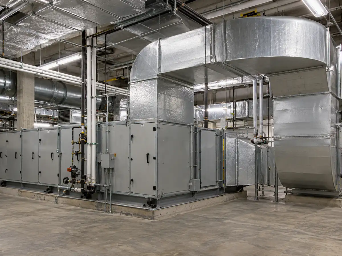
An FCU normally conditions a nearby room or zone; an air handling unit (AHU) normally handles a larger air-distribution and treatment task. Both may contain fans, coils and filters. The distinction is the system role, not just the presence of a coil or the unit’s size.
| Question | FCU | AHU |
|---|---|---|
| Typical service scope | One room or local zone | Multiple rooms or a central air system |
| Air distribution | Direct discharge or shorter local ductwork | Usually larger duct network |
| Outdoor-air treatment | Sometimes integrated; often separate | Frequently a principal design duty |
| Filtration/humidity options | Limited by terminal configuration | Wider centralized treatment options |
| Maintenance | Many dispersed service points | More central plant/service locations |
If you need local thermal control plus treated outdoor air, the answer may be FCU + DOAS/AHU, not FCU versus AHU. For a detailed system-level choice, read our FCU vs AHU comparison.
What Must Be Checked Before and After Installation?
A selected FCU must fit the available space and remain accessible for testing and service. Record the access to the filter, coil, drain pan, water valves or refrigerant connections, motor and controls. Provide a removable panel large enough to remove and replace the filter.
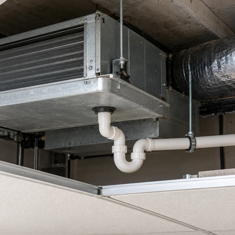
Before installation, confirm the terminal orientation and manufacturer clearances; insulated chilled-water or refrigerant-line routing; access panel size; condensate fall/pump and alarm arrangements where applicable; electrical isolation; suitable valves/balancing devices; and the real duct resistance. For central systems, also confirm whether the plant can provide the specified supply-water temperatures and flow under peak demand.
After commissioning, compare the measured airflow and hydronic temperatures/flow with the design and approved selection. Test thermostat response, valve/fan control sequence, condensate drainage, noise and any BMS points. If a room stays warm, the first checks should include supply conditions, flow, dirty filters, fan speed and duct losses before assuming the coil itself is defective.
| Test | Record and compare | If it does not match |
|---|---|---|
| Airflow at required fan setting | Measured outlet/terminal airflow vs approved design airflow | Inspect filters, dampers, fan setting and external resistance; then remeasure. |
| Hydronic flow and supply/return temperatures | Measured water-side conditions vs approved coil selection and plant mode | Check valves, balancing, water supply conditions; correct and retest. |
| Thermostat and valves | Actual sequence on heat/cool requests vs approved changeover and interlock logic | Correct controls or connections; repeat both modes where available. |
| Condensate drainage and protection | Water test showing free drainage and correct pump/overflow operation if fitted | Correct slope, trap, pump or blockage; repeat drainage test. |
| Sound, vibration and service access | Operating sound at design fan duty and access to filter/pan/valves | Fix noise source or access restriction and check delivered airflow again. |
When an air-to-water heat pump supplies the FCU circuit, the air-source heat pump installation guide covers related water-flow, controls and commissioning checks for that source system. Record the FCU airflow, valve response, drainage and room-control results as separate terminal tests.
Common FCU faults: symptom, first check, next action
| Symptom | First useful check | Likely next action |
|---|---|---|
| Insufficient cooling | Entering-water conditions or matched DX operation, airflow, dirty filter | Restore design conditions and recheck room temperature |
| Weak supply airflow | Filter, fan speed and duct/static resistance | Correct restriction, then measure airflow again |
| Water dripping from ceiling | Drain slope, blockage, pan or pump function | Stop affected operation, fix drainage and water-test the route |
| No heating during shoulder season | Two-pipe changeover status, valve and plant operation | Align controls and supplied water with the requested mode |
| Excessive fan noise | Speed needed to meet duty, duct resistance, vibration mounts | Correct the cause and recheck airflow and sound |
| Room comfortable but stale | Actual outdoor-air supply path and measured ventilation | Rebalance or repair ventilation system separately |
Electrical, refrigerant and pressurized-water service should be performed by qualified technicians. The building’s service plan also matters: a hundred local FCUs mean many filters, motors, drains and valves to maintain.
Frequently Asked Questions About FCUs
Is an FCU the same as an air conditioner?
An FCU is an indoor terminal, not necessarily a complete air-conditioning system. It needs a connected water or refrigerant energy source and the right controls; ventilation may also be separate.
Does a fan coil unit contain a compressor?
A hydronic fan coil normally has no compressor; it gets hot or chilled water from another device. A DX indoor fan coil commonly connects to compressor equipment located elsewhere, so check the matched system.
Can a two-pipe FCU heat one room and cool another at the same time?
Not on a basic common-changeover water loop. The loop supplies one water temperature mode at a time. Mixed simultaneous demands are a reason to consider four-pipe or another system arrangement.
Can I size an FCU just from room square metres or square feet?
No. Area helps with early planning, but solar load, people, humidity, design temperature, ventilation, coil operating conditions and duct resistance can change the needed model. Obtain a room-load calculation and check manufacturer duty data at those conditions.
Why is an FCU not cooling even when the fan runs?
The fan may be moving air without enough cooling from the coil. Check air filter and airflow, water temperature and flow or the DX system’s operating state, valve/control response and actual room load. Verify the corrected conditions before replacing the FCU.
What details should I send when requesting an FCU selection?
Send the room cooling and heating loads, coil medium, water temperatures/flow or matched refrigerant-system details, required airflow and ESP, ventilation route, noise target, electrical supply, controls/BMS needs, ceiling or wall dimensions, and drawings if available.
The Main Point About Fan Coil Units
A fan coil unit uses a fan and coil to condition a local room or zone. Choose hydronic or DX to match the energy system, choose 2-pipe or 4-pipe to match the building’s heating/cooling needs, and choose ducted or direct discharge to match the air path. Final model selection brings together total and sensible capacity, delivered airflow at ESP, sound, drainage, controls and service access at the building’s design conditions. That is how an FCU goes from a simple definition to a system that works reliably in the building.
Need to Review an FCU or HVAC System Direction?
For an initial HVAC system discussion, share your room cooling and heating load schedule, available water or matched refrigerant source, design temperatures, room layout, outdoor-air plan, required airflow and duct ESP, controls needs, noise target and maintenance-space limits. These inputs help identify the system direction and the manufacturer performance evidence needed for a specific FCU comparison. Use the Airproz contact form to discuss project conditions, or browse Airproz’s listed air-conditioning and heat-pump product families for related equipment. For any FCU on your shortlist, request its model-specific selection sheet at the project design conditions.