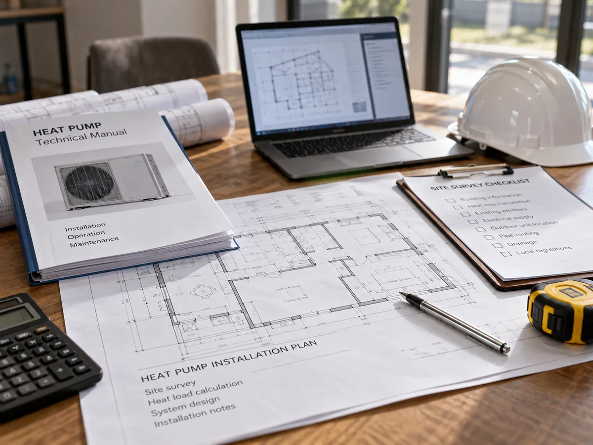
Air source heat pump installation starts with the building’s design heating load and, where needed, cooling load. The installer then prepares the outdoor and indoor locations, connects the appropriate air, water or refrigerant system, and commissions the completed installation. Choose equipment using verified output for the local design weather—not floor area or a nominal kW rating alone. Ducted, ductless and air-to-water systems require different indoor connections and tests. Before work begins, confirm outdoor airflow and service space, drainage, the electrical supply, local approvals and the qualifications required for regulated work. Follow the exact model instructions and keep the commissioning records at handover.
How Is an Air Source Heat Pump Installed?
Installing an air source heat pump starts with the building heating and cooling loads; an air-to-water project also needs its required water temperature. After that, you can choose a suitable unit and position the outdoor equipment. Then connect the appropriate indoor distribution or refrigerant/water pipework, power and controls, and test and set up the complete system. This final testing and setup is called commissioning. It is more than switching the unit on.
The installation work depends on whether you choose ducted air-to-air, ductless air-to-air, or air-to-water heating. Monobloc and split designs also need different pipe connections and safety checks. Radiators, underfloor heating, water flow, the electrical supply, local rules and the exact model also affect the job. Use the steps below as a practical overview, but always follow the manual for the selected model and the rules that apply where the system is installed.
Air Source Heat Pump Installation in 7 Steps
Start with a design load and finish with documented commissioning. Use these seven steps to plan the job. In each step, check the details for your actual system type—ducted, ductless, or air-to-water.
| Step | What happens | What to check |
|---|---|---|
| 1. Calculate design heating and cooling loads where applicable | Check the building and room loads at the relevant winter and summer design conditions. For heating, verify the cold-weather design load; for cooling, check the summer design load where the heat pump will cool. | Do not size the heat pump from floor area or the old boiler rating alone. |
| 2. Check the indoor heating or cooling system | For air-to-water systems, check radiator, floor-loop or fan-coil output at the planned water temperature. For air-to-air systems, check room heating/cooling loads and the required indoor airflow. | If radiators need hotter water than the proposed heat pump can supply efficiently, review emitter sizing. For air-to-air systems, confirm duct capacity or indoor-unit placement before choosing the model. |
| 3. Check capacity at the relevant design conditions | For heating, compare documented output with the winter design load at matching outdoor and indoor or water-temperature conditions. If cooling is needed, check cooling output separately at the summer design condition. | A different rated test point cannot prove capacity at your site. For air-to-water systems include leaving-water temperature; for air-to-air systems include rated indoor-air conditions and required airflow. |
| 4. Verify outdoor-unit location and routes | Check airflow, service space, drainage, noise, pipe routes and the electrical supply. | Confirm Steps 1–4, site constraints and model-specific restrictions before final equipment selection. |
| 5. Complete system connections | Install the water or refrigerant circuit, electrical supply, controls and drainage as shown in the exact model documents. | Use qualified installers where the work or local rules require them. |
| 6. Commission against the design | For air-to-water jobs, check water flow, water temperatures, hot-water and backup-heat controls. For air-to-air jobs, check airflow, condensate drainage, controls and the model-required refrigerant tests. | Simply switching the unit on does not mean the system is properly commissioned. |
| 7. Give the owner the test results and manuals | Record settings, readings, drawings, manuals and anything that could not be fully checked. | Keep these records for future servicing and repeat projects. |
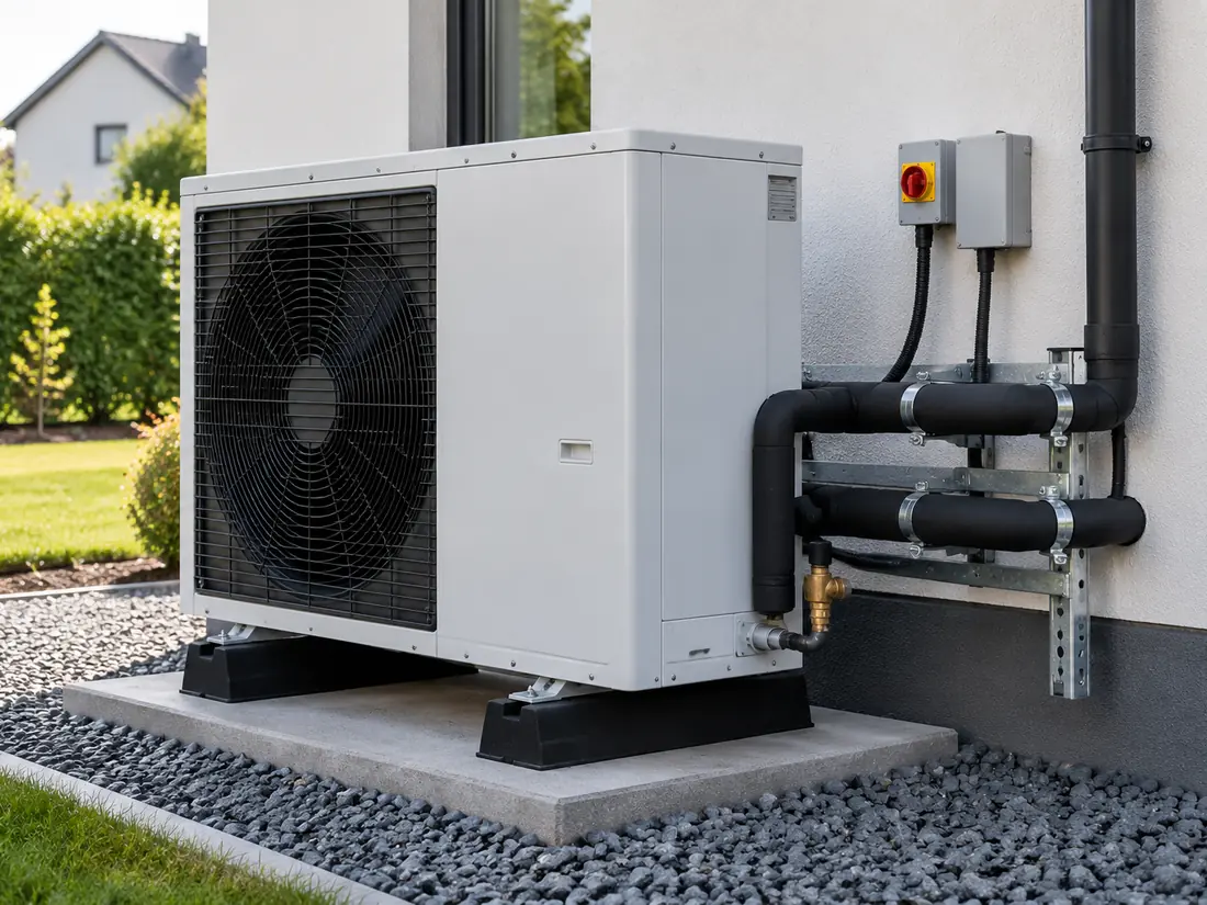
On site, the installer first protects the work area and checks deliveries, access and the approved layout. Depending on the system, the team may isolate and remove old equipment, prepare the outdoor base, fit indoor equipment, make the pipe, duct, drain and electrical connections, and carry out the required tests. The exact order changes with the system and site; regulated work stays with qualified personnel.

Does Installation Change for Ducted, Ductless and Air-to-Water Heat Pumps?
Yes. All three need correct sizing, outdoor airflow, electrical safety and commissioning, but the indoor distribution work is different: ducted systems depend on ducts and airflow, ductless systems on indoor-unit positioning and condensate management, and air-to-water systems on hydraulic flow and water temperature.
| System | Main indoor installation | What you need to check | When this system makes sense |
|---|---|---|---|
| Ducted air-to-air | Air handler, ducts, return air, filters, controls and condensate drain | Room design loads, fan airflow/static pressure, duct leakage and balance; check whether existing ducts are suitable | Whole-home heating and cooling with a viable duct network |
| Ductless air-to-air mini-split | Indoor head(s), secure mount, refrigerant line route, condensate drain and controls | Room-by-room capacity, head location, line-set geometry and drainage; certified refrigerant work where required | Rooms without suitable ducts, targeted zones or additions |
| Air-to-water | Water pipes, pump, emitters, valves, expansion and controls; cylinder when DHW is needed | Required leaving-water temperature, heat-emitter output, flow/head, frost protection and DHW duty | Radiators, hydronic floor systems or existing water-heating distribution |
When to reconsider a system: A ducted heat pump is not a shortcut if existing ducts cannot deliver the required airflow. Ductless equipment may not cover the intended rooms comfortably without suitable indoor-unit positions. An air-to-water system needs compatible emitters, appropriate water temperature, and a reliable hydraulic design. Check these limits before selecting the system type.
How Do Ducted and Ductless Air-to-Air Installations Differ?
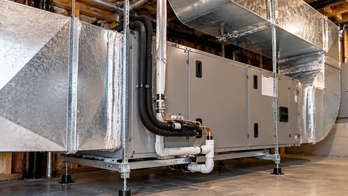
A ducted heat pump requires a usable air-distribution system; a ductless mini-split requires suitable indoor-head locations and line routes. With ducted equipment, check whether air reaches every room and can return to the indoor unit. Measure airflow and the resistance the fan must overcome (external static pressure), then check duct leaks and insulation. Keeping old ducts only makes sense if they can deliver the new system’s required airflow and room distribution.
If the cooling or heating load is covered on paper but the existing ducts have high resistance or too little return air, a larger outdoor unit may not solve the comfort problem. Have the installer measure airflow and external static pressure at the selected fan setting, check room supply and return paths, and repair or rebalance the ducts before changing equipment size.
For ductless systems, check each room’s heat gain and heat loss, indoor-head placement, a drain that runs downhill—or an approved condensate pump when gravity drainage is not possible, service access, refrigerant route limits and outdoor-unit location. Poor head placement can leave occupied areas uncomfortable even with adequate rated capacity. The qualified installer must verify refrigerant-circuit work and commissioning to the applicable regulations and model manual. ENERGY STAR quality installation guidance explicitly includes airflow, refrigerant charge and duct evaluation.
For a multi-zone ductless system, check each room’s design load and the selected indoor unit’s usable output. Then verify the outdoor system’s allowed indoor-unit combinations and available capacity when several zones call for heating or cooling at the same time. Do not add up indoor nameplate capacities and assume the outdoor unit can deliver that total under every condition.

What Changes for an Air-to-Water Installation?
For air-to-water systems, check how hot the water must be, whether the radiators or floor heating can warm each room, and whether enough water can circulate. These are water-system checks, not duct-airflow checks. Check that each radiator or floor loop can meet the room design heat loss at the proposed supply temperature; that pumps and piping can meet the heat pump’s minimum flow across operating modes; and that exposed monobloc water pipes have a credible freeze plan, including during power failure.
If you need to understand how the refrigeration and heating-water circuits connect, review how an air-to-water heat pump works before checking the proposed piping arrangement.
In a cold retrofit, an undersized radiator may need hotter water just when outdoor temperatures are lowest. That combination can reduce available heat-pump output and efficiency. Check each room’s heat loss and radiator output at the proposed water temperature, then check the model’s performance at the same outdoor and water conditions. Improving emitters or reducing heat loss may be preferable to selecting a larger nameplate unit.
Some air-to-water designs also supply domestic hot water, while a standard air-to-air mini-split does not. Treat a DHW cylinder, hygiene control, backup-heating integration and any cooling distribution as separate design decisions. The detailed hydronic checks later in this article apply to this system category, not to every air-source heat pump.
If an air-to-water heat pump will also deliver chilled-water cooling, confirm that the heat pump, connected emitters and controls are designed for that mode. Check the permitted water-temperature limits and insulate chilled-water pipework as specified. For non-condensing radiant floors or ceilings, humid room air can raise the dew point above the cooled surface temperature, causing condensation. ASHRAE’s radiant-cooling guidance explains why the cooled surface must remain above the room-air dew point. Check the specified humidity or dew-point sensing and verify that the controls raise the water temperature or stop cooling when protection is required. Fan coils designed to collect condensate need correctly installed and tested drains instead. Use the exact system instructions to test the protective response; do not assume heating-only radiators or floor loops can cool safely.
What Should Be Checked Before Installing an Air Source Heat Pump?
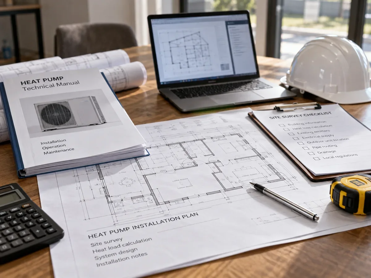
Before installation, check your building load, heat-pump type, outdoor space and power supply. Next, confirm the water temperature or indoor airflow your system needs, plus local permits and the final tests the installer must perform. Resolve these before committing to a model, because a correct outdoor capacity cannot rescue incompatible indoor distribution or a noncompliant installation.
Installation Details to Check Before Selecting Equipment
Record the project inputs before choosing equipment. For air-to-water systems, confirm leaving-water temperature and water distribution. For ducted or ductless air-to-air systems, record room loads, required airflow, indoor-unit placement, and the condition of any existing ducts.
All projects need design loads, local design weather, power details, a proposed outdoor location and the exact model’s limits. Add water temperature, emitter and hydraulic data for air-to-water systems; airflow, return paths and duct condition for ducted systems; or room-by-room indoor-unit placement and line/drain routes for ductless systems.
| What to provide | Why it matters | What happens if you do not have it yet |
|---|---|---|
| Design heat load | Shows how much heat the system must provide on the design day | Do not confirm the exact model yet |
| Design outdoor temperature | Shows the outdoor temperature used for winter sizing | The cold-weather output cannot be checked reliably |
| For air-to-water: required water temperature (leaving-water temperature, or LWT) | Changes how much heat the unit can provide and how efficiently it runs | The air-to-water model and emitter suitability cannot be confirmed |
| Heating / cooling / domestic hot water (DHW) needs | Shows what the system must do and how it needs to be controlled | The suitable product type may change |
| Power supply | Limits which electrical setup and backup heaters can be used | The electrical setup still needs checking |
| Outdoor-unit location | Affects airflow, drainage, service access and noise | Do not fix the final unit position yet |
| Country or region where the heat pump will be installed | Shows which local approvals and certificates may be needed | The final configuration remains unconfirmed |
| Number of units and project type (for multi-unit or commercial installations) | Shows whether the project uses one unit, several units, or central building controls | The multi-unit control plan and scope need confirming |
| For air-to-air: room layout, airflow and ducts or indoor-head positions | Determines whether the indoor system can deliver heating or cooling to occupied rooms | Check duct sizing and fan pressure or indoor-unit positions before selecting equipment |
Before the installation date, agree on equipment access, safe work areas, delivery space and any planned shutdown of heating, hot water or electricity. Ask the installer which services may be unavailable and for how long. Arrange a safe alternative if anyone in the building relies on continuous heating or essential electrical equipment. Check that any required inspections are scheduled before work is covered or closed.
Start With the Heat Load, Not the Old Boiler Rating
First, find out how much heat the building actually needs on a cold design day. You can use floor area for an early discussion, but not for the final model choice. Check the building heat loss, desired indoor temperature and local outdoor design temperature. For air-to-water systems, also check the heating-water temperature. Compare the design heat load with documented cold-weather output before choosing the exact model.
If you plan to insulate walls or lofts, replace windows, or seal major air leaks, tell the designer before the final load calculation. Calculate the load for the building condition the new heat pump will actually serve. If that work changes after sizing, check the load and system choice again rather than using the old number.
The rated kW on a brochure is not a promise of the same output in every condition. Heat-pump output and efficiency change as the outdoor temperature and water temperature change. Compare the building’s cold-design-day load with the model’s documented heating output at matching outdoor and required indoor-air or water conditions. ENERGY STAR also advises against simple rule-of-thumb sizing and recommends using the actual characteristics of the building.
Treat these as three different checks: the catalogue rating is output reported at the stated rating conditions; design-point output is the documented capacity at your project’s relevant outdoor and indoor or water conditions; delivered performance depends on the installed airflow or water flow, defrost, controls and distribution. A successful mild-weather start-up cannot by itself prove winter design-day performance. Record what was tested and arrange seasonal verification if a critical condition could not be observed.
Also check part-load operation. A unit that covers the coldest day may still cycle excessively in mild weather if its minimum stable output exceeds the load served by the active zones. Check documented modulation limits together with zoning and system water volume or airflow. Do not oversize only to create a nominal safety margin.
Before the exact model is chosen: For an air-to-water heat pump, confirm the design heat load, outdoor design temperature, required leaving-water temperature, and documented output at that point. Leaving-water temperature is the water temperature leaving the heat pump. For air-to-air systems, compare design heating and cooling loads with model data at the relevant indoor and outdoor conditions, then check airflow and room distribution.

Check the Radiators, Underfloor Heating and Required Water Temperature
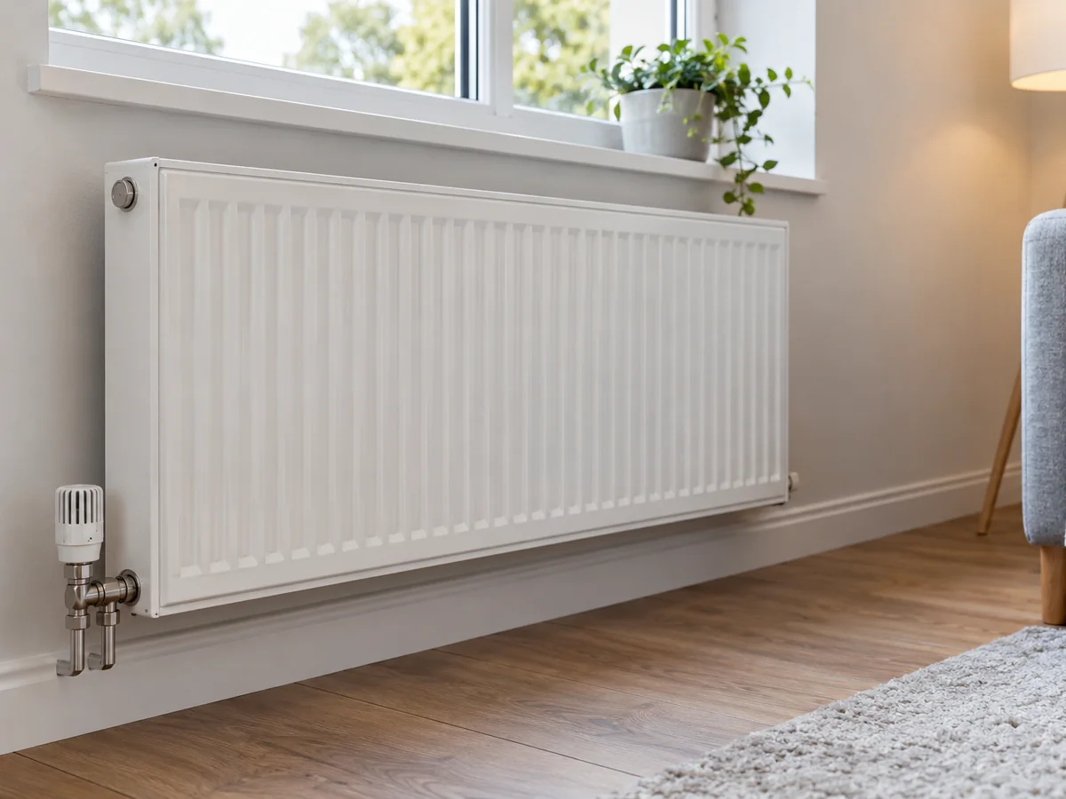
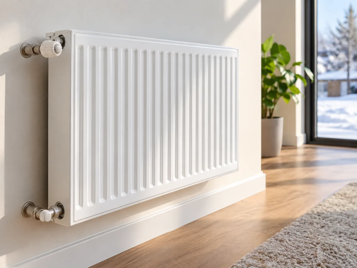
Your radiators, underfloor heating or fan coils must be able to heat the rooms at the water temperature the heat pump will use. These room-heating devices are called heat emitters. If they only provide enough heat with very hot water, you may need a different heat pump, larger radiators, or another system setup.
The aim is not simply to make the water as hot as possible. Higher water temperatures can reduce heat-pump efficiency. For an existing building, check the heat loss of each room and the size of its radiators. Do this before deciding that every radiator must be replaced, or that none of them need changing. For a new building, plan the emitters, pipe sizes and heating zones together with the heat pump from the start.
For a boiler-replacement project, the air-to-water heat pump versus boiler comparison explains why emitter temperature and site conditions can change which heating system is suitable.
How Is Installing a Monobloc Different From a Split Heat Pump?
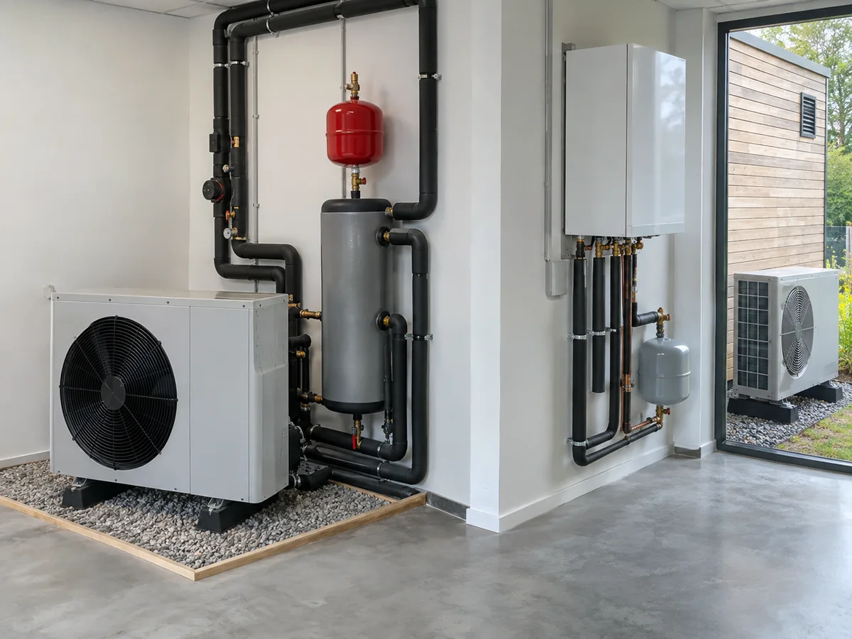
A monobloc air-to-water heat pump has its refrigerant circuit inside the factory-built unit. Your installer normally connects this unit to the indoor heating system using water pipes. A split system runs refrigerant pipes between the outdoor and indoor equipment. This changes what you need to watch. Monobloc systems need careful freeze protection for outdoor water pipes. Split systems need refrigerant work on site, which may require qualified personnel under local rules. The monobloc-versus-split comparison here concerns air-to-water equipment. A ductless air-to-air mini-split connects the outdoor unit to indoor air units using refrigerant lines and has separate checks for indoor-unit placement, condensate drainage and required qualified refrigerant work.
For a monobloc with water outside the building, review freeze protection in three states: normal powered operation, loss of power, and an extended shutdown. Insulation slows heat loss but does not guarantee protection. Use only the protection method, fluid and drain-down procedure allowed by the exact product and system design; document who checks it before winter.
Where Should the Heat Pump Outdoor Unit Be Installed?
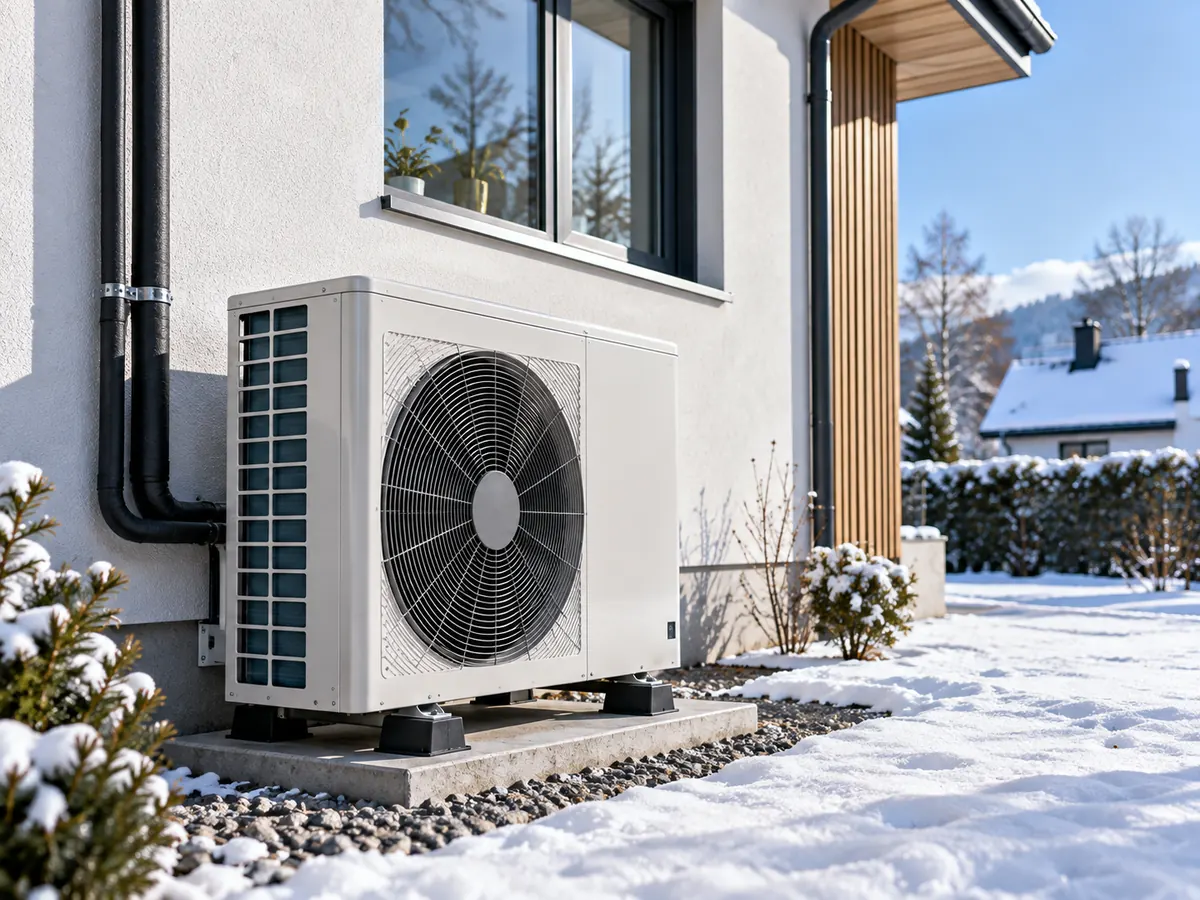
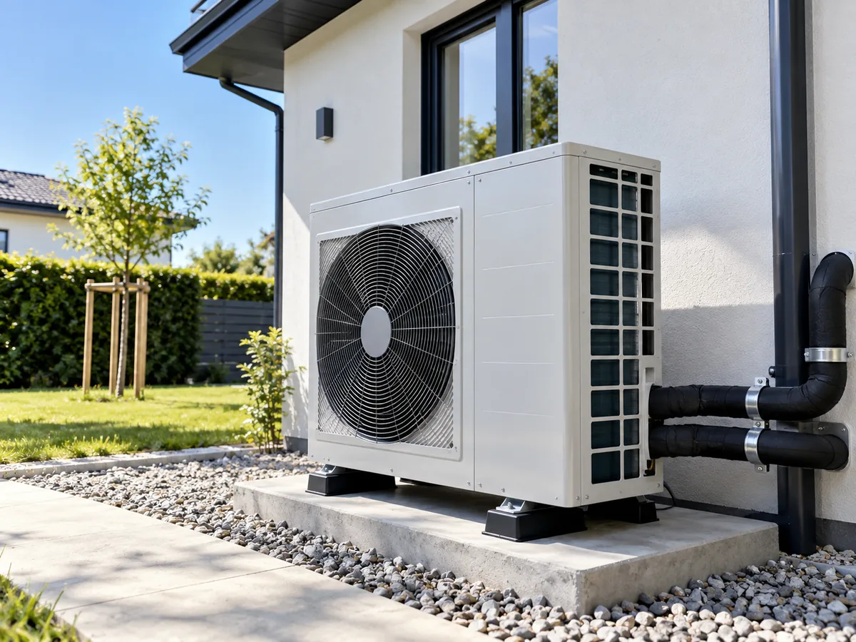
A heat pump outdoor unit needs enough open space for air to enter and leave freely. It also needs safe defrost-water drainage, service access, acceptable noise and vibration, and a practical route for pipes and electrical connections. The cabinet fitting physically is not enough. There is no single clearance distance for every model. Check the dimensions and air-space requirements in the exact installation manual before fixing the unit position.
Current MCS installation guidance for air source heat pumps specifically calls for manufacturer-led siting, consideration of chilled-air recirculation, avoidance of nuisance to neighbours, vibration control and safe condensate discharge. These are useful principles beyond the UK even though the legal requirements differ by jurisdiction.
Use the installation manual for the exact model and installation geometry. Clearances can change when the unit faces a wall, sits in a corner, is installed in a bank of units or has obstacles above the discharge path.
Outdoor Unit Location: When the Site Works and When It Needs Changing
A location is acceptable only if the actual clearances, airflow, drainage, noise and maintenance access all work together. Use the following comparison to reject an otherwise convenient but unsafe position.
| What to check | The location is suitable when | Change the location when |
|---|---|---|
| Air intake | The exact model clearance can be maintained | A wall, fence or landscaping restricts the inlet |
| Air discharge | The discharge path remains open | Cold air is likely to recirculate into the coil |
| Service access | Panels and service components remain reachable | The unit fits physically but cannot be serviced |
| Defrost water | Water has a safe, durable discharge route | Water can freeze at the base, path or occupied walkway |
| Snow / flooding | The base height matches the project exposure | The coil, drain or electrics can be buried or flooded |
| Noise | The sound level has been checked at nearby homes, windows or other sensitive locations using the real site layout | The unit faces a sensitive window or boundary without review |
| Pipe / electrical route | The route remains within model and project limits | The proposed pipe or cable route exceeds a model limit or would block safe servicing |
If a corner location restricts airflow and the defrost drain can freeze on a walkway, changing only the mounting height will not solve both problems. Recheck the exact inlet/discharge clearances, snow exposure, safe drainage path, noise at nearby rooms and service access together. If these cannot all be met, move the unit or revise the site arrangement.
Can Walls or Fences Restrict Heat Pump Airflow?
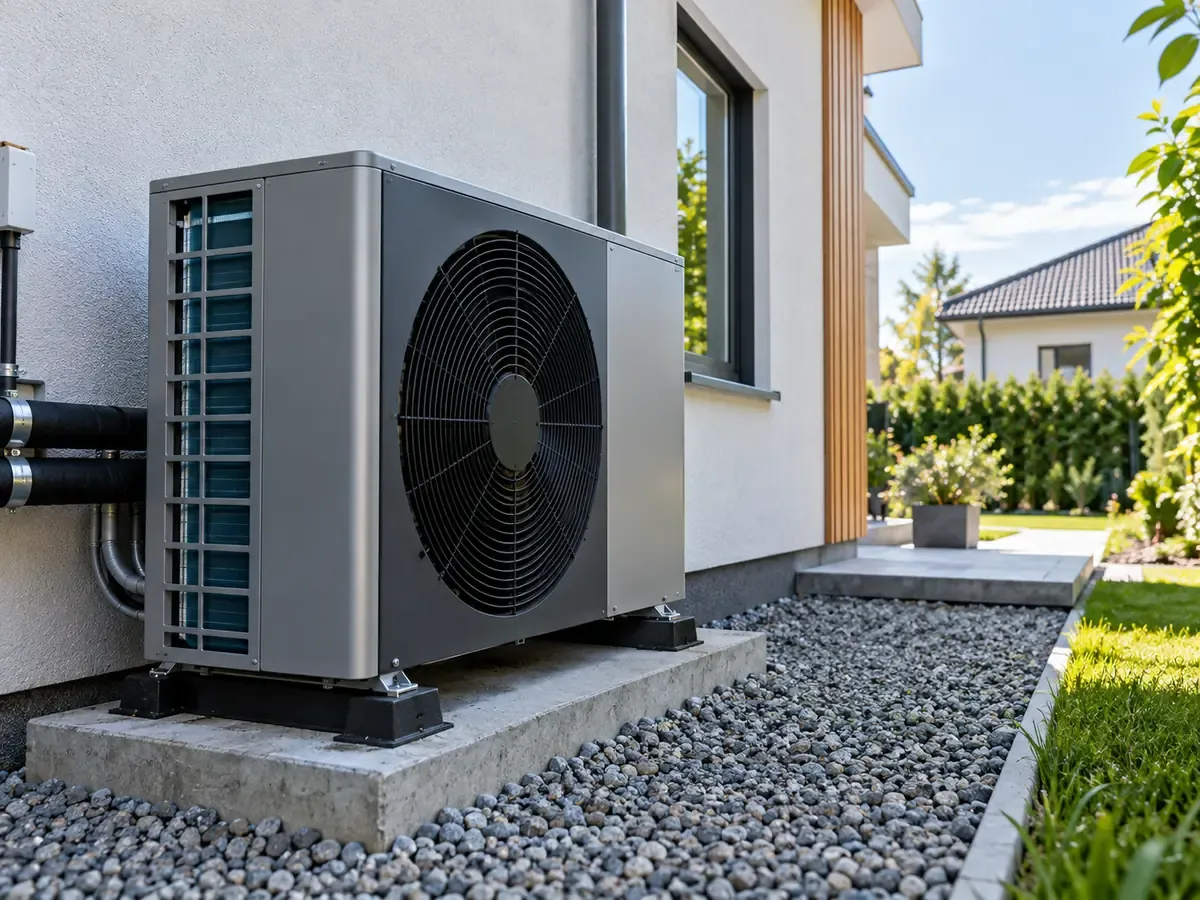
An outdoor unit can look well positioned but still perform poorly if discharged cold air is pulled back into the coil. If the fan pulls this colder exhaust air back into the outdoor coil, the heat pump has less useful heat available. It may frost or defrost more often and deliver less heating. Narrow alleys, deep recesses, solid screens and opposing units can all create this risk.
How Should the Heat Pump Be Mounted and Kept Accessible?
The base must be stable, level and able to support the unit over its service life. The mounting method should also manage vibration without allowing the unit to move or distort. Avoid fixing the unit to lightweight structures or locations that can transmit compressor vibration into bedrooms or occupied rooms unless the manufacturer provides a suitable mounting solution.
Leave enough access to remove panels, reach valves and electrical compartments, clean the heat exchanger and replace major service parts. A location that technically fits but cannot be serviced is not a good installation location.
Defrost Water, Snow, Ice and Flooding
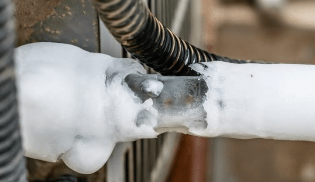
In cold weather, frost can build up on the outdoor coil. The unit periodically melts that frost in a process called defrosting. That water must leave the unit and remain harmless after it reaches the ground or drain. Poor drainage can produce ice under the unit, block drain paths, create slip hazards or refreeze against the base.
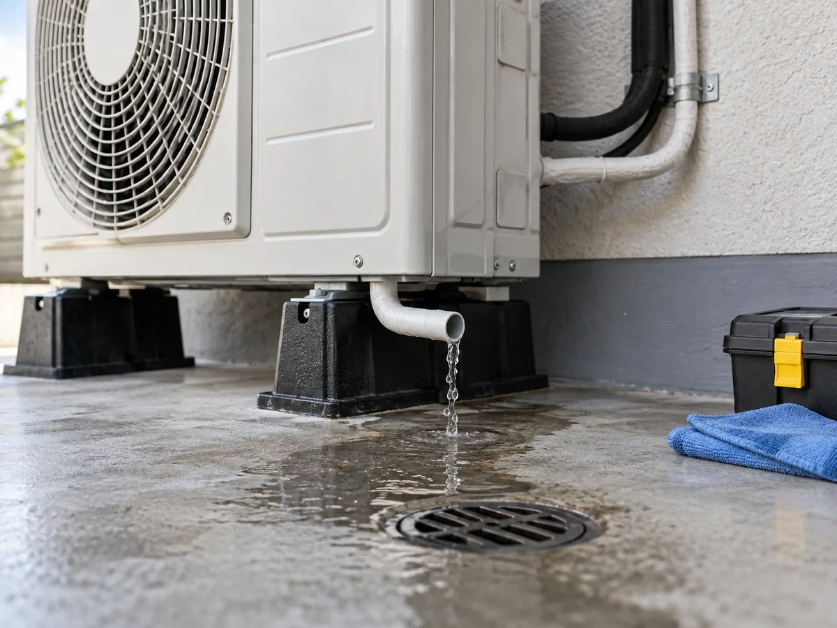
In cold climates, evaluate expected snow depth, roof runoff and the risk of frozen drain paths before choosing base height and drainage details. If the site floods, check how high the outdoor unit and electrical connections must be mounted to avoid exposure under local rules. In coastal or chemically aggressive environments, corrosion exposure should also be checked against the product’s approved installation conditions.
The correct detail is model- and climate-specific. Do not copy a stand height, drain heater or tray arrangement from another brand without confirming that the selected model supports it.
How Can Heat Pump Noise Affect Where You Install It?
Sound power describes noise emitted by the equipment; sound pressure describes noise received at a particular location. Two published dB(A) numbers are not comparable unless the measurement quantity and conditions match. Use the specified operating mode and the proposed receiver position when assessing a bedroom or property boundary. Distance, reflective walls, corners, barriers and multiple outdoor units can change the sound level received at the assessment location.
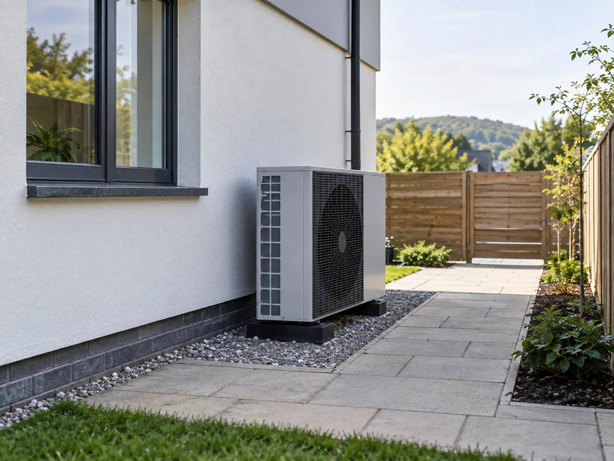
For example, England’s MCS planning methodology evaluates the manufacturer’s sound power data together with distance, directivity and barriers at an assessment position. Other markets use different rules. The practical lesson is to check the sound level at the actual nearby window or property boundary, taking distance and barriers into account—not just the dB(A) number in a brochure.
If noise compliance is uncertain, move the unit, change orientation, reassess barriers or select a product with suitable acoustic data before purchase. Do not depend on a decorative enclosure that compromises airflow or service clearance.
Plan the Connection Route Before Fixing the Outdoor Unit
The shortest route is not always the best route. Before the final equipment choice, plan the water or refrigerant pipe route, insulation, wall penetrations, electrical supply, controls, drainage and future service access. Each model has limits for pipe length and height difference. Check the selected model’s installation manual before choosing where to mount the indoor and outdoor equipment.
Where pipes, cables or refrigerant lines pass through walls, the installer must restore the building’s weather and air barriers and protect the lines from damage. Keep required insulation continuous outdoors and use suitable sleeves, seals and fire-stopping where the wall assembly or local code requires them. Do not assume that a weatherproof cover alone seals the wall opening.
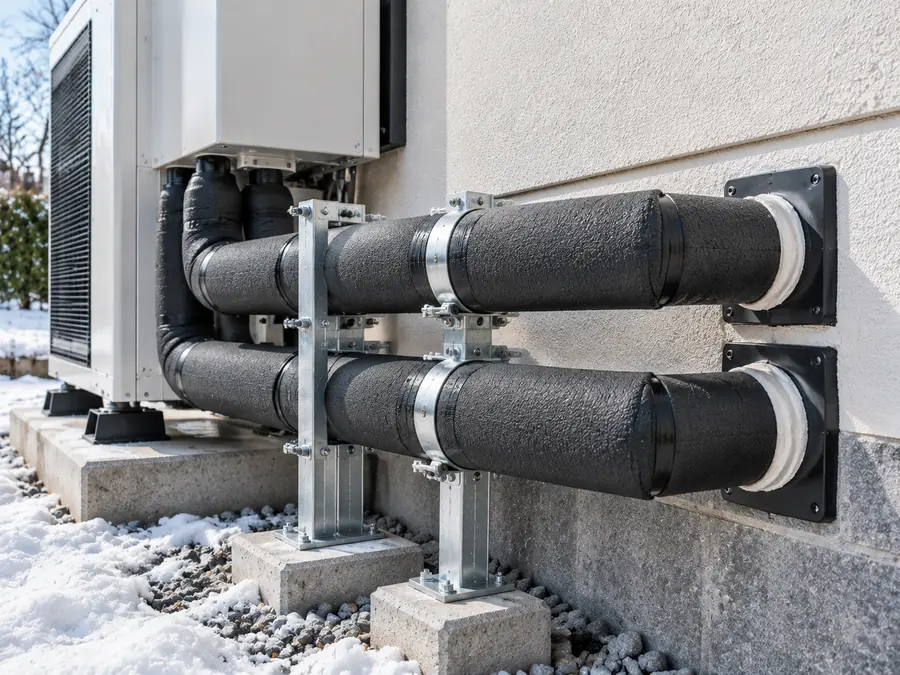
For monobloc systems, the external water circuit is exposed to ambient conditions. Insulation, pipe supports and freeze-protection strategy therefore become part of the installation design. Freeze protection may involve controls, valves, fluid strategy or other manufacturer-approved measures, but it should never be assumed that one method is suitable for every unit. Power-failure conditions are particularly important because active frost protection cannot be relied on when the system has no power.
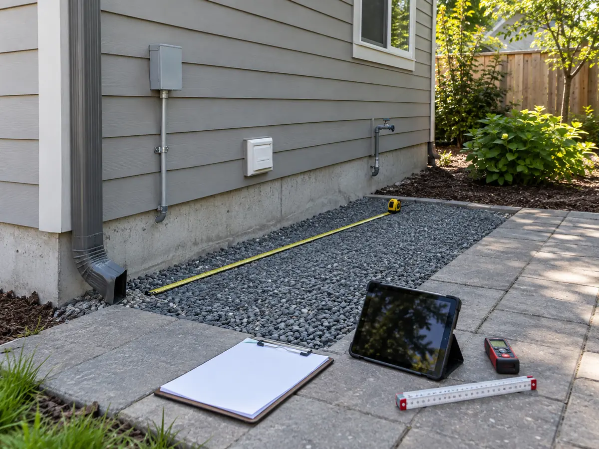
Once you have marked the route on the site plan, check where pipes and cables will pass through walls. For air-to-water systems, include water flow and insulation; for air-to-air systems, include the refrigerant line route and condensate drain. This guide explains what you, your designer and your installer should confirm before ordering and installing the equipment. The exact model manual and local rules always come first.
For split systems, refrigerant pipe sizing, length, elevation, evacuation, leak testing and charge adjustment must follow the exact manual and applicable refrigerant regulations. These are qualified-installer tasks, not DIY steps.
For a field-connected refrigerant circuit, the qualified installer should document the leak/pressure checks, evacuation and final refrigerant charge verification required by the exact model. The test conditions and acceptance limits come from that manual; this article does not set universal pressure or vacuum targets.
The exact refrigerant and equipment design may introduce additional location, room-size, charge, piping or safety requirements. Have the qualified installer check the model instructions, applicable refrigerant safety rules and the proposed indoor/outdoor locations before work begins. Do not apply another model’s charge allowance or clearance to this installation.
Electrical Supply and Controls Must Match the Actual Configuration
Before installation, have the electrician confirm the required voltage, phase, frequency, circuit protection and isolation switch for the exact model. Include any backup heater, pump and control loads in the electrical plan. A heat pump that fits thermally may still be unsuitable if the site power supply or available capacity cannot support the selected configuration.
For a model-specific example, the R32 monobloc space heating heat pump specification table shows how voltage, phase and rated water-flow requirements vary by configuration. Its published models use 50 Hz supplies, so the table is not a substitute for verifying a 60 Hz site or the exact model manual.
Check the allowed simultaneous electrical loads, not just the compressor rating. Auxiliary heaters, pumps, fans and domestic-hot-water functions can change the required supply and protection. If available power is limited while winter heat demand is high, the designer and electrician must check the heater staging, equipment capacity and electrical service together before finalizing the system.
If the available electrical supply is limited, list the compressor, fan, pump, hot-water and auxiliary-heater loads that the selected controller may run together. Compare each permitted operating combination with the electrical design, especially in cold weather when backup heat may be needed. If a permitted combination exceeds the available supply, the design must address the supply or use a staging or priority strategy explicitly supported by the equipment instructions. Check that any restricted heater operation still leaves enough heat for the building, and have the electrician and commissioning team verify the final arrangement.
Check separately whether utility notification or connection approval is required where the system will be installed. Some jurisdictions also require network notification or approval. In Great Britain, the Energy Networks Association publishes a heat-pump connection and notification process; other countries use their own utility and electrical rules.
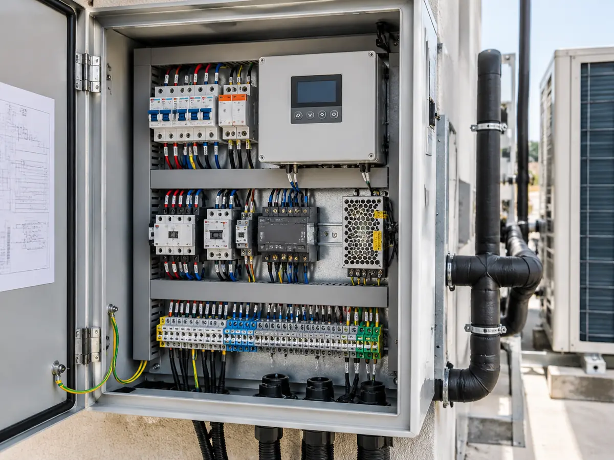
Put the sensors, pumps, valves and control connections on one clear wiring or control diagram. The installer can then test that each part starts and stops as intended. This includes weather sensors, room controls, DHW sensors, pumps, valves, building management system (BMS) contacts and internet-connected gateways. The commissioning team can then check that the system works in the intended order.
What Is Different About Cold-Climate Heat Pump Installation?
For a cold-climate installation, first check that the unit can provide enough heat at your area’s cold design temperature. Then plan safe defrost drainage, snow clearance, backup heat if needed, and protection during power outages. The fact that a unit is allowed to operate at a low temperature does not establish that it can carry the building load there.
- Capacity: compare the design heat loss with documented net output at the outdoor design point, including relevant indoor-air or water-temperature conditions.
- Location: protect coil airflow from drifting snow and ice without boxing in the outdoor unit.
- Drainage: check that defrost water does not refreeze beneath the base, on a walkway or in the intended outlet.
- Backup: size and control supplemental heat only where the load comparison and operating strategy require it.
- Power outage: for outdoor monobloc water circuits, verify an approved protection strategy even when powered frost controls are unavailable.
Why Is Low-Temperature Capacity Different From an Operating Limit?
An operating-limit temperature only says the equipment is permitted to run there; it does not say how much heat it delivers. Output can decrease as the air gets colder, while building heat loss increases. Compare the building’s heating demand with the heat pump’s documented output in the same cold conditions. The DOE cold-climate heat pump sizing guidance explains the design-point selection method; actual equipment selection still needs the chosen model’s data for the project conditions. If the unit cannot cover the full load, specify when the backup heater or second heating system should take over. Use performance data that includes defrost losses where available. Also check electrical input; the rated-condition coefficient of performance (COP) may not match cold-weather operation.
The outdoor temperature at which the heat pump can no longer meet the building load is its capacity balance point. Some dual-fuel systems also have a cost-based changeover setting, based on energy prices. These are not automatically the same setting. Have the designer check the actual heat-pump output, backup capacity, energy prices where relevant, and thermostat controls before setting compressor lockouts or backup staging. Do not copy a fixed changeover temperature from another installation.
At the winter design point, the building may need more heat while the heat pump provides less; defrost cycles can further affect net delivered heat. Compare documented capacity under the relevant conditions with the design load, then define when approved backup heat should operate and whether the electrical supply can support it. If performance data do not cover the critical condition, mark the sizing decision as unverified rather than assume the rated COP or operating limit proves it.
Do not assume insulation prevents freezing during an outage. For monobloc exposed water pipework, stored heat and active circulation can run out. Verify the selected manufacturer’s instructions, local climate and chosen freeze-protection method before installation.
Make Sure the Indoor Water System Can Provide the Right Flow and Temperature
For an air-to-water heat pump, make sure enough water can move through the unit in every heating mode. Check the pump’s ability to overcome pipe resistance (pump head), the radiators or floor loops, the system water volume and the controls. A heat pump may be correctly sized and still fail if valves close off circulation, pipes have too much resistance or rooms need a higher water temperature than the design assumed.
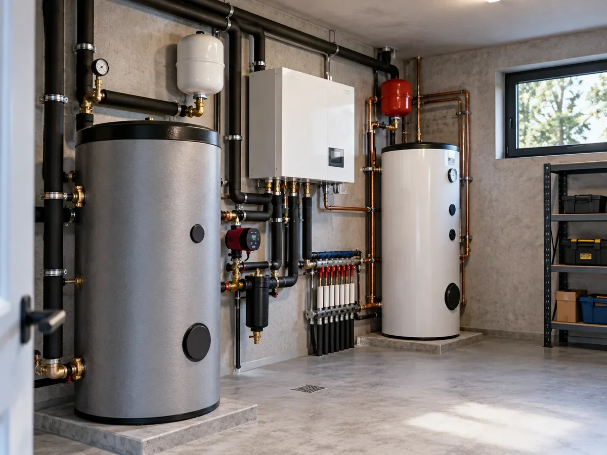
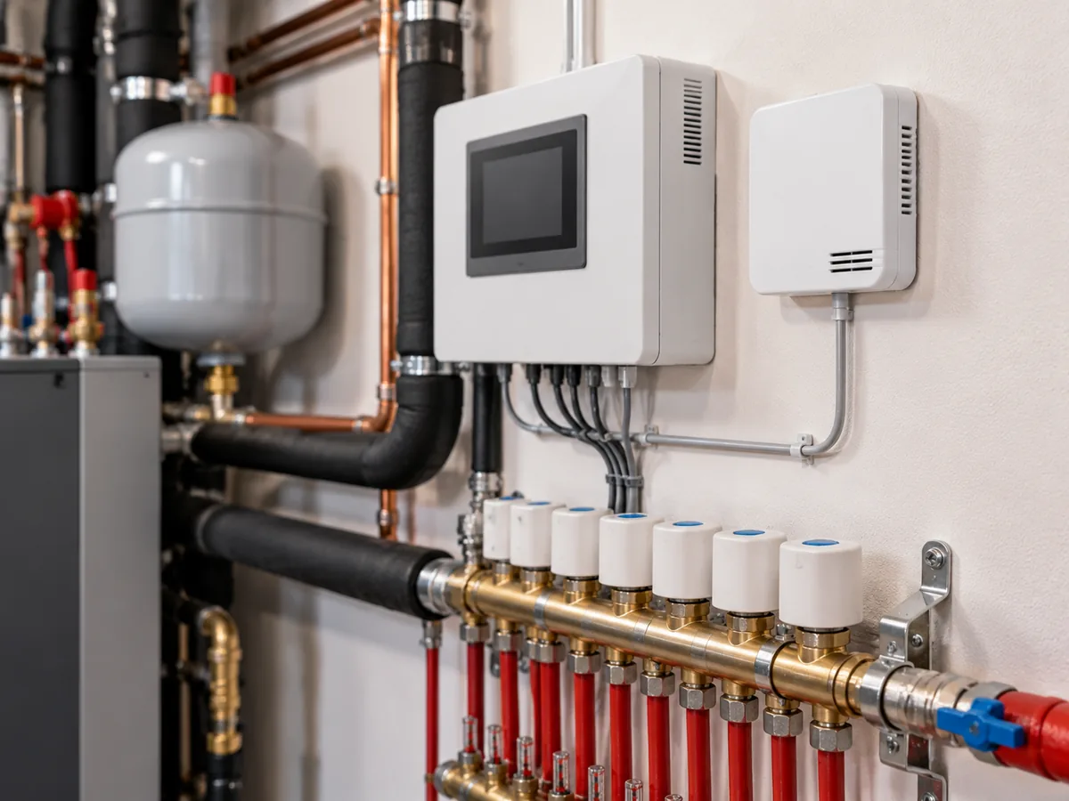
An air-to-water heat pump is only one part of the building’s water system. Good operation also depends on pipe resistance, pump capacity, water flow, air removal, expansion volume, filters, balanced radiators or floor-heating loops, and the control setup. A buffer tank or other added water volume can help with some minimum-flow, cycling or storage needs. A low-loss header can separate pump circuits, but none of these parts should be added automatically; the system design must show why they are needed.
Check the minimum and normal water-flow requirements in the selected model documents. Then make sure the pipes and pump can provide that flow in every normal operating mode. If the building has several heating zones or control valves, make sure closing a zone cannot reduce heat-pump flow below the allowed minimum.
Check the worst normal valve and pump combinations, not just a full-open heating circuit. When zones close or a domestic-hot-water valve changes position, confirm there is still an approved circulation path through the heat pump where required. Verify pump head, minimum flow and any minimum-water-volume requirement against the model manual. Add a buffer or hydraulic separation only when the design shows it solves a defined problem.
For an air-to-water circuit, check that the pump can deliver the design flow against the resistance of the complete flow path, including relevant pipework, valves, filters, emitters and heat exchangers. Compare the available pump performance at that flow with the calculated circuit pressure loss, using ASHRAE’s hydronic pump-and-system curve guidance as a technical reference; a pump’s advertised maximum flow is not its delivered flow in this system. Check the permitted valve and pump states, including any domestic-hot-water changeover. During commissioning, verify flow using the measurements or approved checks provided for the exact installation. If it is too low, locate the restriction or control fault before specifying a larger pump or buffer tank.
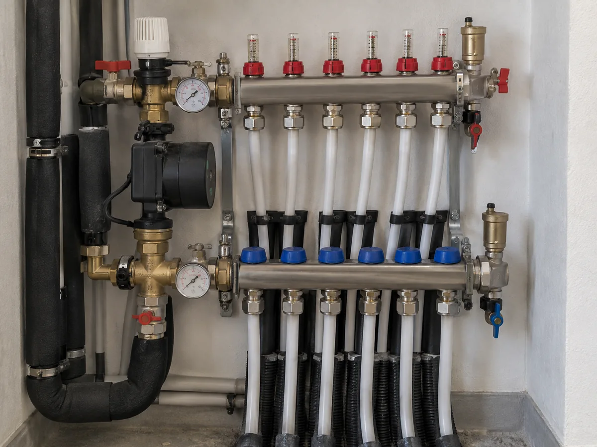
External and internal water piping should be insulated where required for heat loss, condensation and freeze control. Air vents belong at appropriate high points, drains at suitable low points, and strainers or filters must remain accessible for service.
Check Domestic Hot Water and Backup Heating Separately
If your system will also heat water for showers and taps (domestic hot water, or DHW), check the tank size, heat-transfer coil, sensor position and controls. The installer must also meet local hot-water hygiene and safety rules. A cylinder that worked with a boiler is not automatically suitable for a heat pump because the heat-transfer coil may be too small.
If the controls give domestic hot water priority, space heating may pause or change output while the cylinder reheats. Check the building’s winter heating demand, cylinder heat-exchanger capacity, expected hot-water draw and allowed control sequence together. Verify that any backup heat and electrical supply are compatible with the selected arrangement.
During a cold spell, domestic-hot-water reheating may interrupt space heating when the building has little spare heating capacity. Compare the expected hot-water demand and cylinder recovery duty with the cylinder heat exchanger, the building’s winter heat loss and the controller’s return-to-heating sequence. If the planned interruption could leave rooms below the design comfort requirement, review the cylinder arrangement, control priority and any approved backup heat before assuming a larger nominal heat-pump rating will solve it. Confirm the permitted modes in the equipment documents and record the handover settings.
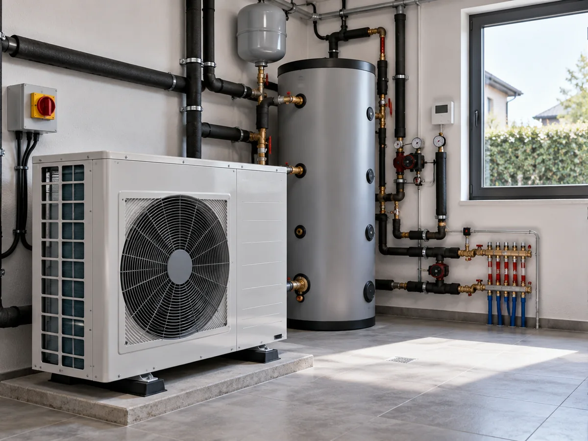
An electric backup heater, boiler or other extra heat source also changes the electrical load and control settings. This extra source is called auxiliary heat; when two different heat sources work together, the system may be described as bivalent. Set the control rules before commissioning so backup heat does not hide an undersized heat pump or run when it is not needed.
If an existing gas boiler may stay as a second heat source, the heat pump vs gas boiler comparison explains how winter heating demand, radiator water temperature, local energy tariffs and full installation scope affect that choice.
For a clearer view of air-to-water system components and flow paths, Airproz’s separate air-to-water heat pump diagram and heat pump schematic guides can be used alongside the model installation manual. The installation guide here focuses on decisions and verification rather than replacing manufacturer schematics.
How Long Does an Air Source Heat Pump Installation Take?
There is no fixed installation duration. On-site work for a relatively straightforward residential project may take several days, but this is not a project-wide promise. Design, permits, electrical supply upgrades, distribution changes and access constraints can extend the overall schedule. Confirm the actual work and testing with the installation team before committing to a date.
The full project may also include design visits, permits and equipment delivery before work begins. Ask for three dates separately: when on-site work starts, when heating or hot water may be unavailable, and when commissioning and any required inspection will be complete.
| Project condition | Typical schedule effect | What to confirm before work starts |
|---|---|---|
| Existing radiators or other heat emitters are already suitable | Reduces retrofit work | Check that they provide enough heat at the planned water temperature |
| Radiators or fan coils need replacement | Adds room-by-room work | Confirm which units will be changed and what pipe changes are needed |
| Electrical supply needs upgrading | Can add coordination and approval time | Confirm the supply, electrical protection and backup-heater load |
| Difficult pipe or cable route | Adds installation work and access time | Confirm the route and wall or floor openings before equipment delivery |
| Several heat pumps or building management system (BMS) controls | Adds control and commissioning work | Confirm how the units start, stop and communicate |
How Much Does Air Source Heat Pump Installation Cost?
Installed cost is the total for equipment, labor, any distribution or electrical upgrades, permits and commissioning—not the outdoor-unit price alone. To estimate your installation cost, specify the building location, heat-pump type, heating/cooling needs and any changes to ducts, radiators or electrical supply. Ask the installer to price each part of the work separately. There is no single installed price that applies to every country, building or heat-pump system.
| What the quote includes | Cost driver | What each installer should include in writing |
|---|---|---|
| Heat pump and indoor equipment | Design-duty capacity, type, operating conditions and compatible controls | Exact model/configuration, included accessories and warranty conditions |
| Air distribution or hydronic upgrades | Duct repair/addition, air handler, radiator changes, floor loops, pumps or cylinders | Room-by-room scope, materials and what remains unchanged |
| Connections and electrical work | Pipe/line length, route, supply capacity, backup heaters and isolators | Specified circuit/pipework work and any service upgrade exclusions |
| Site work, permissions and removal | Base, mounting, drainage, access, permits, demolition and disposal | Permits, site reinstatement and old equipment removal clearly included/excluded |
| Testing and handover | Commissioning time, measurements, controls, balancing and customer instruction | Named tests, measured results, documents and aftercare responsibility |
| Rebates and tax incentives | Local market, eligibility, funding, timing and documentation | Gross installed quote, confirmed program details and separately identified potential benefit |
Compare quotations against the same building loads, documented model operating points and installation scope. For ducted systems, include duct repairs, return-air paths and airflow tests; for ductless systems, include indoor-head locations, refrigerant routes and condensate drainage; for air-to-water systems, include emitter, water-pipe and control changes. Check electrical work, permissions and commissioning in each quote. A lower initial price is not necessarily a lower complete installed cost.
A lower equipment price or a higher advertised COP does not by itself establish the lowest operating cost. Compare documented performance at the same relevant conditions, expected backup-heat use, distribution changes and commissioning scope. Annual cost estimates need site weather, building load and a defined operating strategy; do not assume a universal saving percentage.
Do You Need Permits or a Qualified Installer for a Heat Pump?
Permits and contractor qualifications depend on where the project is located and on the work involved. Homeowners can gather plans, access requirements and installation quotes, but refrigerant-circuit work, wiring, pressure-system work and final safety checks may legally require certified or licensed professionals. Even if a product is advertised as pre-charged or “DIY-ready,” check which connections and inspections local rules still require.
- Before ordering: ask the local building authority which mechanical, electrical, planning or environmental permissions apply.
- Before connecting refrigerant: confirm technician certification and the exact model procedure.
- Before any electrical changes: check supply capacity, isolation, protection, permits and licensed-electrician requirements.
- Before scheduling commissioning: confirm who will issue inspection results, test records and warranty paperwork.
- Before relying on a rebate: verify application timing, qualifying model, approved installer and funding availability with the program operator.
When comparing installers, ask who will complete the load calculation, verify the selected model and distribution system, obtain required permits, perform regulated connections, and record commissioning results. Confirm who handles any unresolved seasonal tests and how defects will be reported. The answers should be specific to your system type and local rules, not just a general promise of professional installation.
Can a Homeowner Install an Air Source Heat Pump as a DIY Project?
You can measure the available space, collect plans and prepare access for the installer. Do not assume that a DIY-labelled heat pump allows you to connect refrigerant lines, change fixed wiring or sign off safety tests yourself. In the United States, EPA Section 608 requires technician certification for activities that open or connect regulated refrigerant circuits, including conventional mini-split line connections. Electrical licenses, mechanical permits and final inspections are determined separately by state and local authorities. Split, monobloc and factory-sealed products may have different on-site duties.
For air-to-water projects, hot-water safety, expansion, pressure testing and hydronic commissioning remain important even when the refrigerant loop is sealed at the factory. For air-to-air jobs, verify condensate disposal, airflow and refrigerant commissioning. If you cannot establish which tasks are lawful and who will sign off the installation, do not begin regulated work.
How Should You Check Heat Pump Installation Rebates in 2026?
Before you sign a contract, look up the rebate program for your address. Check the eligible heat-pump models, approved-installer rules, application deadline, whether preapproval is needed and what proof you must submit. In the United States, state and utility programs vary; a currently listed program is not proof that a specific project qualifies.
This is a U.S. federal credit rule, not a statement that all assistance ended. State, local and utility incentives are separate programs; check the exact location, equipment eligibility, installation date and available program funding before including any expected benefit in the budget.
For U.S. homeowners, the federal Section 25C Energy Efficient Home Improvement Credit does not apply to qualifying property placed in service after December 31, 2025, under current IRS guidance. Do not apply old federal tax-credit amounts to a 2026 installation. See the IRS guidance on the end of the Section 25C credit; other jurisdictional programs require independent confirmation.
Who Checks Equipment Data, Site Design and Installation?
Equipment documents define each model’s allowed conditions, dimensions, connections and installation limits. The system designer checks building loads and the indoor distribution design. The installation team checks actual site conditions, permits, regulated electrical or refrigerant work, commissioning and the handover record. Manufacturer documentation does not replace the site-specific design or local approvals.
| Equipment information to verify | Site designer and installer responsibilities |
|---|---|
| Documented model heating/cooling performance at the project design conditions | Site load calculation, room distribution and emitter or duct design |
| Operating temperature limits, clearances and required connections from the exact manual | Site-specific outdoor-unit position, foundations, drainage and service access |
| Equipment electrical data: voltage, circuit and any auxiliary loads | Electrical supply assessment, protection, utility notification and local code compliance |
| Hydraulic, refrigerant, control and installation diagrams required for the system type | Field piping/ducts and refrigerant work where applicable, flushing and testing, controls and commissioning |
| Product and applicable certification information needed for the intended market | Permits, planning permission, technician qualifications and inspection or approval records |
What Should You Check Before Ordering and Installing a Heat Pump?
The installation overview shows the work sequence. Before final equipment selection, resolve questions about site conditions, distribution, electrical capacity and documented performance at the project design conditions. Confirm these details before equipment is ordered or on-site work begins.
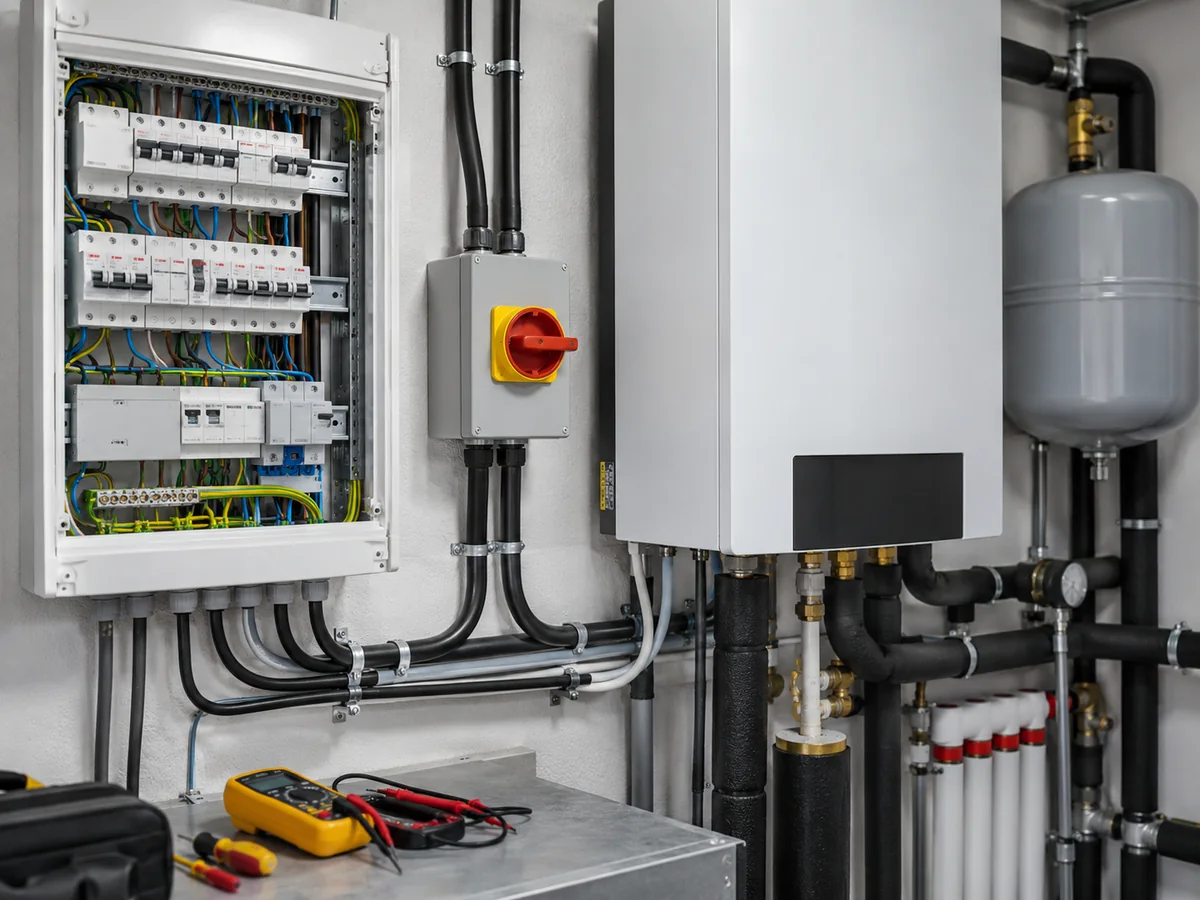
- Before selecting equipment: record the building and room loads, outdoor design weather, heating-water or indoor-air conditions, power supply, site limits and applicable approvals. Compare model output at matching conditions, not nominal kW alone.
- Before ordering: confirm ducted, ductless or air-to-water distribution; any relevant monobloc or split design; heating, cooling and hot-water needs; outdoor airflow, drainage, noise, pipe or line routes and accessories. If a critical input, approval or site constraint remains unknown, hold the decision and assign responsibility for verification.
- During installation and handover: use the exact model documents and local rules for mounting, piping, ducts, electrical and control work. For split systems, follow the applicable qualified refrigerant procedures. Test the completed system against its design and keep readings, settings, drawings, manuals and unresolved seasonal checks.
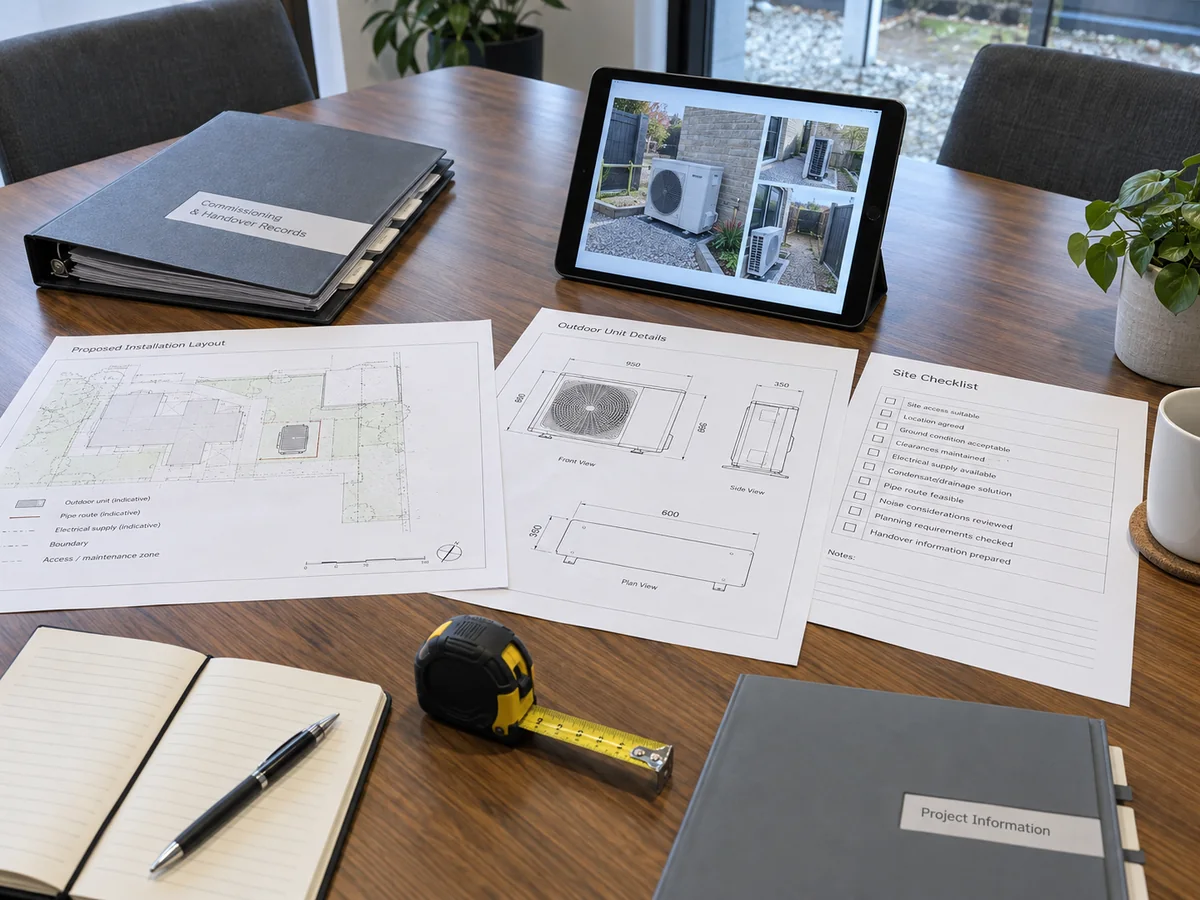
What Should the Installer Test Before Handover?
The job is not finished when the heat pump turns on. Before handover, the installer should check safety, airflow or water circulation, controls and measured operation against the system design and exact manual, then record the results. An air-to-water job needs hydraulic verification; an air-to-air job needs measured air distribution, refrigerant-system checks and condensate tests as applicable.
When Is the Installation Actually Complete?
A heat pump is not ready for handover simply because it powers on. The installer should check electrical safety, controls, normal operation and the applicable airflow or water-flow conditions against the approved system design and the exact model instructions. Record the results and identify any conditions that could not yet be verified rather than treating a successful start-up as proof of design-weather performance.
MCS installation guidance, for example, requires commissioning to a documented procedure so the system can be checked against the standard, the manufacturer’s requirements and the system design. Keep the installer’s test readings and final settings. They show how the system worked at handover and give the service team a starting point if a fault appears later.
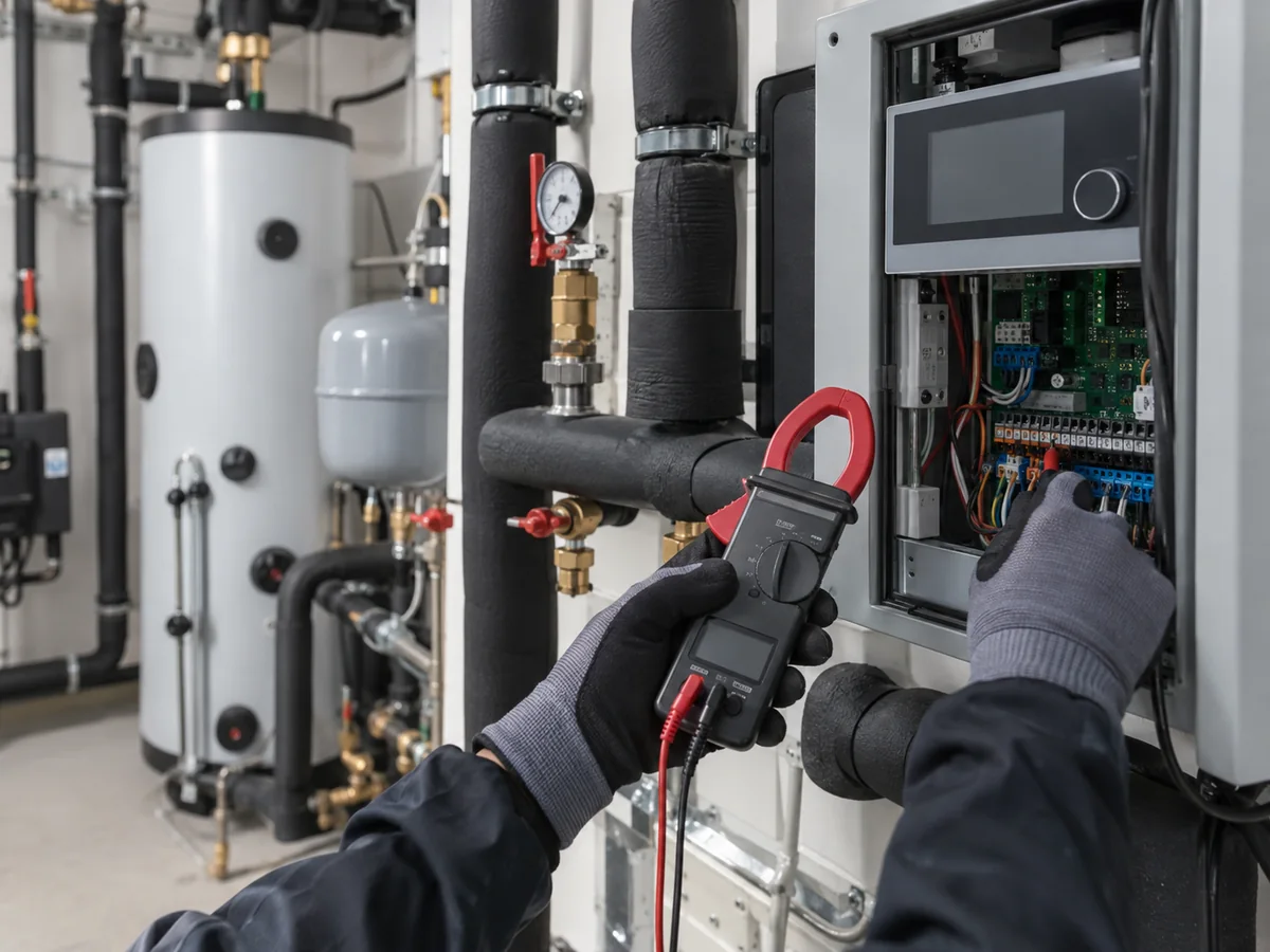
For an air-to-water project, record the outdoor condition and the water flow and return temperatures. Also record actual water flow where available, relevant water pressures, control settings, weather-compensation settings (which adjust water temperature as outdoor weather changes), hot-water operation and backup-heater settings. Verify that pumps and valves respond correctly in each intended mode and that emitters receive the designed flow.
Where weather compensation or zone controls are fitted, check more than the saved settings. Use the model’s approved commissioning procedure to confirm that the outdoor sensor reads plausibly, the requested heating-water temperature responds in the intended direction, and the permitted valve and pump actions occur without violating minimum-flow limits. Record the input condition, the controller command, the observed response and any unresolved fault. Do not infer successful control operation from a setpoint screenshot alone.
Observe a heating run long enough to identify unstable cycling, flow errors, abnormal noise or poor air separation. Where cold-weather conditions allow, confirm that defrost water can drain without refreezing around the unit. If the weather is too warm to verify a design-critical cold-weather function, document that limitation rather than claiming it has been proven.
For each critical handover check, record the test condition, measured result and the acceptance criterion from the design or model manual. If cold-weather capacity, defrost drainage or backup staging cannot be observed, list it as an open seasonal test, name the responsible party and define the weather or operating condition that will trigger the follow-up. Do not call an unobserved condition fully verified.
For ducted air-to-air equipment, record supply/return airflow, relevant static pressure, duct balance and leakage findings, thermostat and changeover settings, condensate flow, and refrigerant checks required by the installation manual. For ductless equipment, verify indoor-head operation, each zone’s airflow and drainage, heating/cooling mode changes and the regulated refrigerant procedure. These do not replace the water-flow and temperature measurements required for hydronic systems. For conventional low-voltage controls, the linked guide explains terminal functions; communicating and proprietary controllers still require their own approved diagrams and qualified testing.
Ask the installer to demonstrate the normal heating and cooling controls, any backup-heat mode, and what happens during defrost, including any brief heating pause or visible vapor outside (depending on the model). Show which filters and outdoor clearances the owner may safely maintain, which alarms require a service call, and how to shut the system down safely if instructed by the manual. Record the service contact and hand over the owner’s manual. Do not treat an electrical or refrigerant repair as homeowner maintenance.
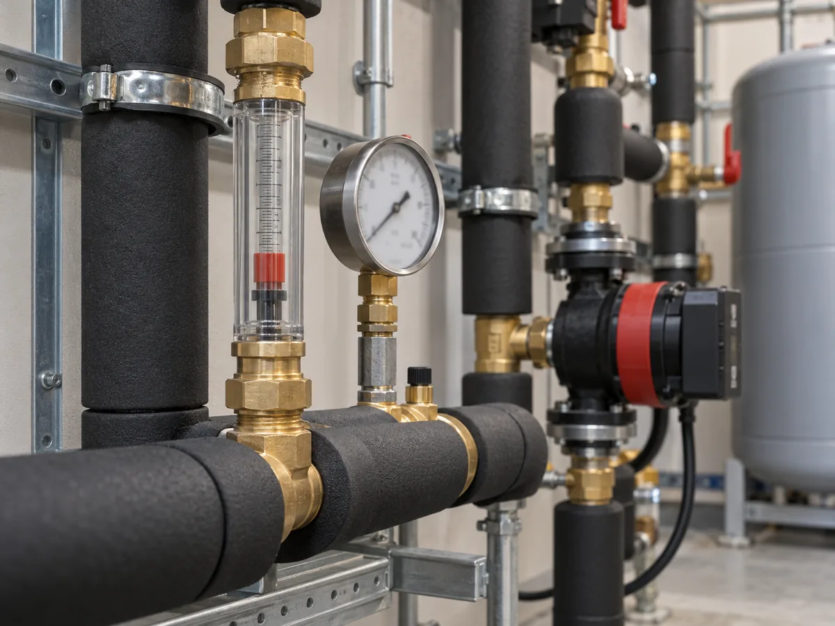
What Documents and Test Results Should You Get?
Before handover, keep:
- exact outdoor and indoor model / configuration;
- serial numbers where applicable;
- design heating and, where applicable, cooling loads, outdoor design conditions, and the required water or indoor-air conditions;
- electrical and control schematics, plus the hydraulic or duct/indoor-unit layouts for the selected system;
- commissioning readings and controls, including relevant water flow and temperatures or airflow and fan pressure;
- DHW, weather compensation, condensate, frost protection, defrost and auxiliary-heat settings where used;
- for ducted or ductless systems, duct balancing or indoor-unit airflow results, condensate tests and the applicable refrigerant-circuit test records;
- product manuals, warranty conditions and installer documentation;
- relevant market approvals, notifications or permit records; and
- any condition that could not be verified during commissioning.
For B2B projects, keep site-specific drawings, control settings and test readings for each installation. They help the project team compare sites without assuming identical conditions or performance.
Common Heat Pump Installation Problems and What to Check
Common problems include choosing equipment without checking cold-weather output, blocking the airflow or water flow, poor drainage, missing freeze protection and incorrectly set controls. Match each symptom to the actual mechanism and record a test result before changing the equipment or installation layout.
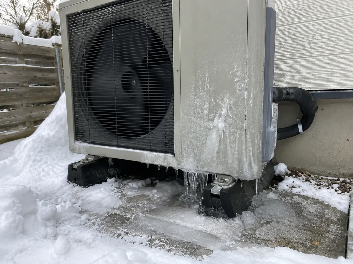
Use the tables to connect each installation problem with its likely cause, the measurement needed and the corrective action. Simple visual checks can identify site issues, but refrigerant-circuit and regulated electrical tests belong to appropriately qualified installers.
Start safely: record the fault code, operating mode, outdoor weather and affected rooms. Check only accessible, non-invasive items such as blocked vents, a dirty user-serviceable filter, control settings or visible drain ice. Have a qualified installer measure airflow or water flow and investigate electrical or refrigerant faults. Stop and seek professional help if there is an electrical hazard, suspected refrigerant leak or unsafe ice buildup.
When there is no immediate safety hazard, a heat pump may briefly pause normal heating during a defrost cycle; check the model instructions before treating a short pause as a failure. If room temperatures continue to fall, alarms repeat or unsafe ice builds up, record the weather, operating mode, setpoint and fault history and contact the qualified installer. The installer should compare these observations with the normal sequence and actual airflow or water-flow checks before changing equipment size or controls.
| Installation problem | Why it happens | Typical symptom | How to check it | When to catch it | What to do next |
|---|---|---|---|---|---|
| Unit selected from nominal kW only | Cold-weather output is not checked | Backup heat runs too early or rooms do not reach the target temperature | Compare the heat load with verified output at the design outdoor and water temperatures | Before the final quote / order | Choose another unit or revise the system before ordering |
| Outdoor air recirculation | Cold discharge air is pulled back into the inlet | Lower heating output and more frosting or defrosting | Check the real wall and fence layout against the model clearance drawing | Before the final unit position is fixed | Move or turn the unit |
| Poor defrost drainage | Water refreezes near the base | Ice buildup, blocked drains or slip hazard | Review drainage path and cold-weather condition | Before installation | Redesign the base / drainage using approved details |
| Inadequate monobloc freeze protection | Stationary external water freezes during cold or power-off conditions | Restricted flow, leaks or component damage | Review the freeze strategy for powered and power-loss cases | Design stage | Use a manufacturer-approved protection strategy |
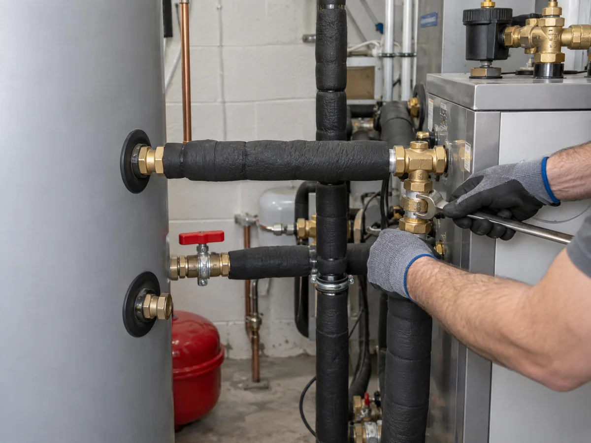
| Installation problem | Why it happens | Typical symptom | How to check it | When to catch it | What to do next |
|---|---|---|---|---|---|
| Water temperature is higher than expected | Radiators or other heat emitters need hotter water to heat the rooms | Lower efficiency or not enough room heat | Check each room’s heat loss and emitter output at the planned water temperature | Before the exact model is confirmed | Use larger emitters or revise the system choice |
| Poor water flow | Pipe resistance, closed valves, trapped air or dirty filters restrict the water | Flow alarms, frequent starts and stops, or uneven heating | Measure water flow and temperature difference, then inspect filters, valves and air vents | During design and commissioning | Balance or clean the system, or change the water-system design |
| Vibration transmitted to structure | Rigid mounting or unsuitable surface | Low-frequency noise indoors | Inspect base, mounts, flexible connections and affected rooms | Before installation + commissioning | Correct mounting to the manufacturer requirement |
| Control or sensor error | Wrong sensor placement, wiring or control logic | Unstable temperature or unnecessary backup heat | Compare wiring and settings with the approved control schematic | Commissioning | Correct the configuration and recommission |
| Air-to-air installation problem | Why it happens | What you may notice | What the installer should verify | Corrective direction |
|---|---|---|---|---|
| Low airflow or high duct static pressure | Undersized, obstructed or poorly balanced ductwork limits airflow | Poor room comfort, fan noise or reduced capacity | Measure delivered airflow and external static pressure against the model’s fan data; inspect filters, returns, leakage and balance | Correct the duct or fan arrangement; do not compensate by guessing a larger unit |
| Indoor head coverage or blocked return | Indoor-unit placement or obstructions prevent intended room circulation | Uneven room temperatures | Compare room loads, indoor-unit locations, discharge paths and allowed clearances | Change the layout or equipment selection within model limits |
| Condensate drain failure | Drain routing, slope or pump operation prevents water removal | Water leaks, staining or nuisance shutdowns | Check drainage and approved condensate pump operation under relevant cooling conditions | Correct the drain/pump arrangement before handover |
| Refrigerant-circuit installation error | Incorrect field piping or unverified circuit can impair performance and safety | Poor capacity, faults or abnormal operating behavior | Qualified personnel verify required leak tests, evacuation and charge/line limits under the exact model manual | Correct and document the work using authorized procedures |
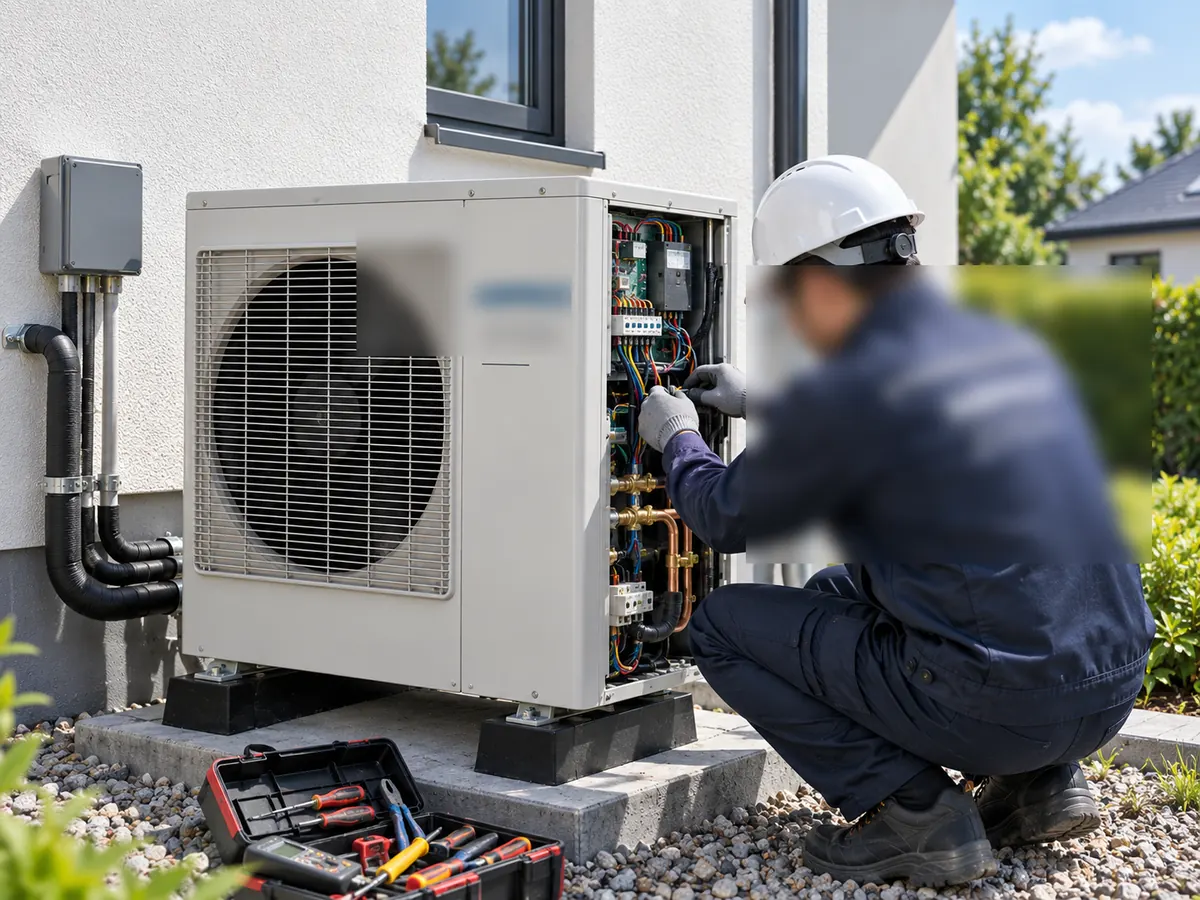
Which Heat Pump Installation Rules Apply Where You Live?
Heat-pump installation requirements vary by location. The local team must confirm building and electrical permits, refrigerant-work qualifications, planning limits and any utility notification before installation. Product certification and model manuals do not replace site-specific approvals.
In the United Kingdom, applicable heat-pump design and installation requirements depend on the scheme and local jurisdiction. The linked current MCS standards document covers heat-pump design; installation and commissioning requirements must be checked separately. In England, England’s planning rules may determine whether permission is needed or permitted-development conditions apply. Electricity-network notification or approval may also be relevant in Great Britain. In the United States, EPA Section 608 requirements apply to covered refrigerant-service activities, including specified connections on conventional split mini-splits; separate state and local rules govern permits and electrical licenses.
Check the rules that apply to the installation address and equipment type. An approval or design standard from one country should not be treated as the legal requirement in another.
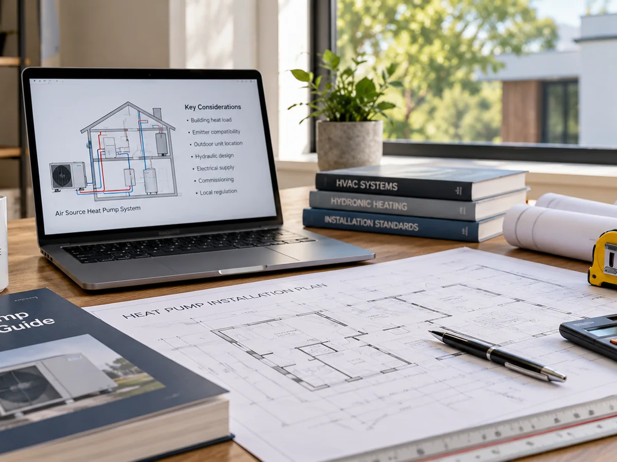
Which Technical Documents Should Be Available Before Installation?
For the exact heat-pump model, obtain its installation manual, dimensional and clearance drawings, operating limits, electrical requirements and performance tables at the relevant design conditions. Air-to-water installations also require hydraulic requirements; ducted and ductless installations need the applicable airflow, refrigerant-line and drainage instructions. Verify any approvals required in the intended market.
For a model-level example, the R290 monobloc heating heat pump page lists water connections, electrical data and rated test conditions; confirm the exact model manual and design-condition performance before using those values.
Use the capacity tables to check the actual design operating point, the dimension/clearance drawings to approve the site layout, the electrical and control diagrams to prepare connections, and the commissioning procedure to define handover tests. If a model-specific document is missing, record the corresponding decision as unverified rather than substitute a generic brochure.
If the project requires market-specific approval documents or formal technical submittals, verify that the documents apply to the exact configuration. An unverified certificate, operating limit or site-specific claim must not be treated as approved.
Installation Information to Keep With Your Project
Keep the design heating and cooling loads as applicable, outdoor design temperatures, room distribution requirements, power supply, proposed outdoor location, noise-sensitive boundaries, line or water-pipe routes, drainage and frost risks, and required permits. For air-to-water systems, record leaving-water temperature, emitters and water-flow needs. For air-to-air systems, record duct or indoor-unit layouts and airflow requirements.
Site photos, a plant-room sketch, room plans and a list of existing radiators or other emitters can clarify the site constraints. For multi-unit installations, record whether units operate independently, as a cascade, or through a building management system (BMS). Record the project country, any specified approvals and unit quantity where relevant.
Frequently Asked Questions
How is an air source heat pump installed?
First, calculate the building’s heating and cooling loads where needed. For air-to-water systems, check required water temperature; for air-to-air systems, check ducts or indoor-unit placement and airflow. Then choose a suitable unit, confirm the outdoor location and pipe route, complete the water or refrigerant connections, connect the electrics and controls, and commission the system. Always follow the exact model manual and local rules.
How long does an air source heat pump installation take?
There is no fixed duration. On-site work for a straightforward home project may take several days, but design, permits, electrical upgrades, radiator or duct changes, difficult routes and commissioning can extend the whole project. Confirm the site work before setting a completion date. Ask the installer which days heating, hot water or electrical power may be interrupted, and whether an inspection or follow-up test is needed before final handover. These interruptions depend on the equipment being replaced and the work required in your home.
Where should a heat pump outdoor unit be installed?
Choose a place with enough open space for air to enter and leave the unit. It also needs safe defrost-water drainage, service access, acceptable noise and vibration, and a practical route for pipes and cables. Check the exact model manual because there is no one clearance rule for every heat pump.
How much clearance does a heat pump outdoor unit need?
There is no single clearance that works for every model. The required space depends on the heat pump, airflow direction, nearby walls, fences, corners, overhead obstacles and other units. Check the exact model drawing before you fix the final position.
Does an air source heat pump need a drain?
An air source heat pump produces water when it defrosts. That water needs somewhere safe to go. Plan the drainage before installation so water does not freeze under the unit, block the drain or create a slippery walkway.
Do all radiators need to be replaced when installing an air source heat pump?
No. Check how much heat each room needs and how much heat each existing radiator can provide at the planned heat-pump water temperature. Some radiators may already be large enough, while others may need to be replaced or enlarged.
What information is needed to select an air source heat pump?
Use the design heating and cooling loads where applicable, local outdoor design temperatures, power supply and installation limits. For air-to-water systems, also check leaving-water temperature and emitters. For air-to-air systems, check room loads, airflow and indoor-unit or duct design. Compare the exact model’s documented output at the required conditions before confirming the choice.
Can a heat pump be sized using floor area alone?
No. Floor area is only a rough starting point. Final selection depends on the building’s design heating and cooling loads where applicable, outdoor design weather, model output at those conditions and the requirements of the air or water distribution system.
How much does an air source heat pump installation cost?
The total installed cost depends on equipment, building conditions, changes to ducts and air handlers, or to radiators and water pipework, electrical work, site access, permits and commissioning. Ask for an itemized local quotation with the same design and installation scope before comparing prices.
Do you need a permit to install an air source heat pump?
Permits vary by jurisdiction and work type. Check mechanical, electrical and planning requirements with the local building authority before ordering. Any utility notification, inspections and licensed-contractor requirements should be confirmed as part of the project.
Can you install a heat pump yourself?
You can collect measurements and plan access, but regulated electrical, refrigerant and pressure-system work may require licensed or certified professionals. In the United States, EPA Section 608 certification applies to relevant refrigerant-circuit work on conventional mini-splits.
What should installers test on ducted or ductless air-to-air heat pumps?
Check indoor-unit drainage and mode switching, measured airflow and controls. For ducted equipment, measure fan pressure against the duct resistance (external static pressure) and check duct condition; for split refrigerant circuits, verify the model-required tests and charge under applicable technician rules. Document results at handover.
What Should You Confirm Before Installation Is Complete?
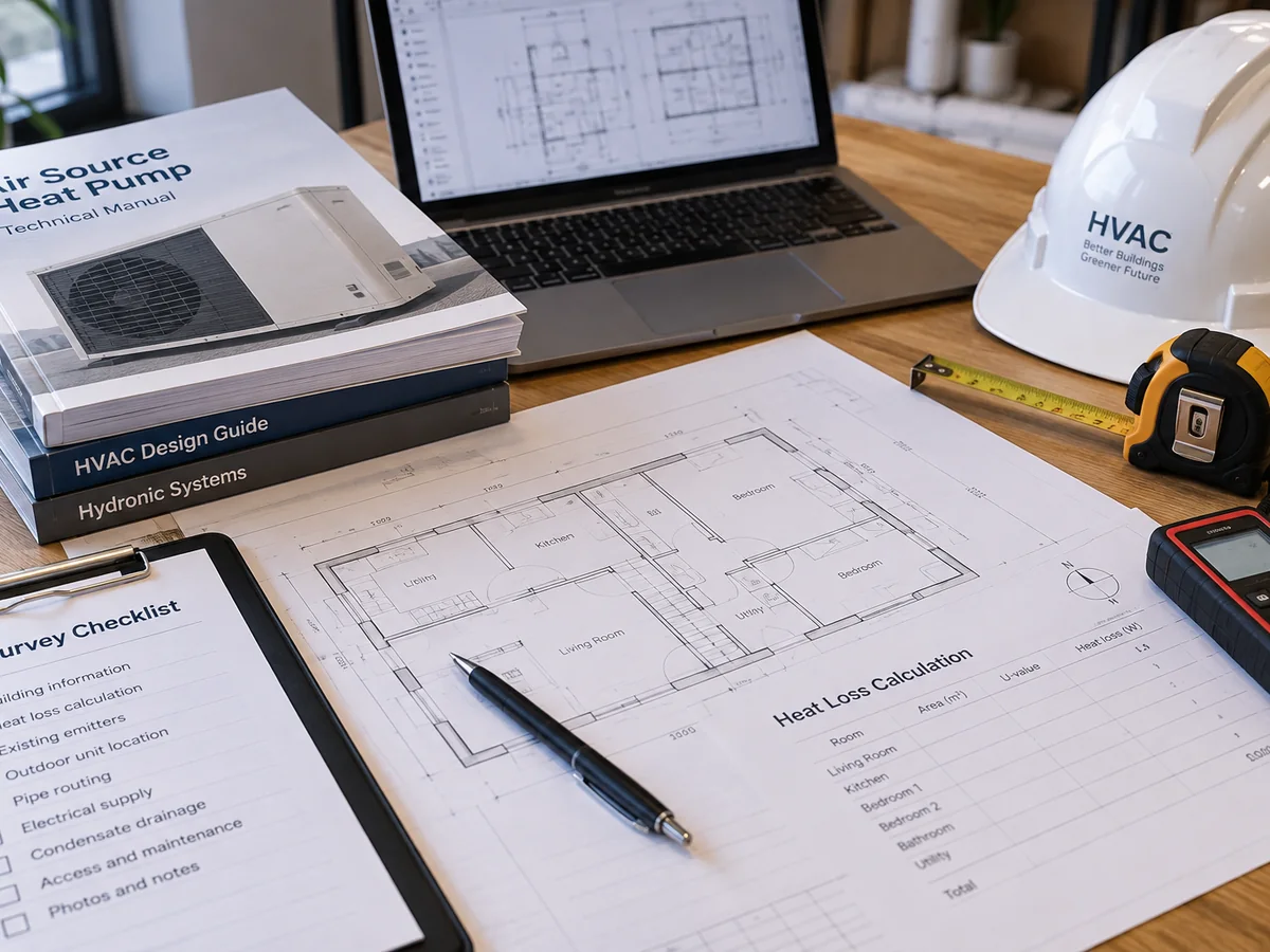
Before installation, confirm building and room loads at the relevant design weather, then compare the exact model’s output at the required indoor-air or heating-water conditions. Check outdoor airflow and access, room distribution, electrical capacity, drainage, pipe or line routes, frost protection where needed, permits and who performs regulated work. At handover, keep the measured airflow or water-flow results, controls and safety checks, model documents and any outstanding seasonal tests. If a critical design input, approval or safety requirement is missing, do not approve that part of the installation merely because the unit powers on.