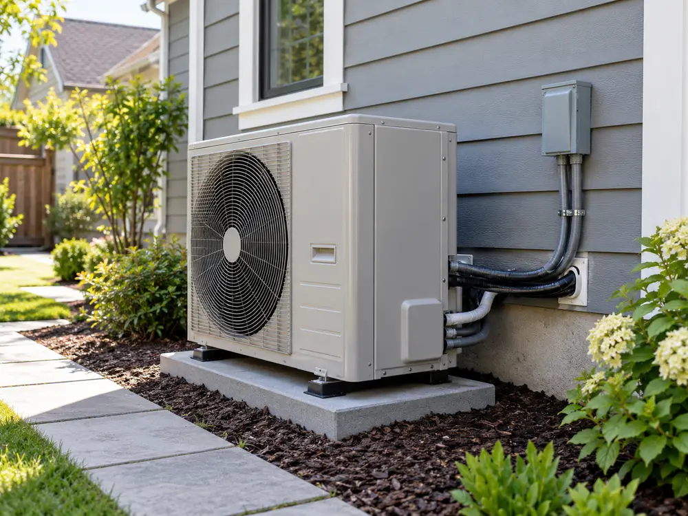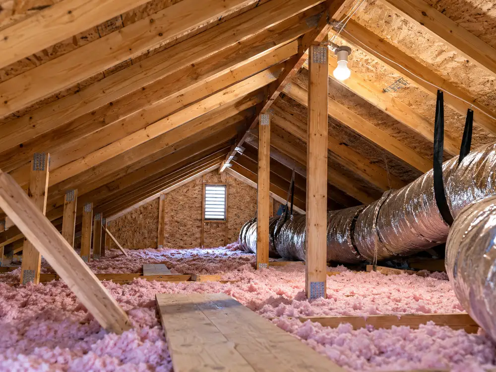
Air conditioning connection usually means the refrigerant pipes, electrical supply, control cable, and condensate drain that allow an indoor AC unit and an outdoor unit to work together. Refrigerant is the fluid that carries heat through the sealed cooling circuit. Condensate is the water that forms on the cold indoor coil. In a typical split air conditioner, two refrigerant lines link the units, electrical and communication circuits operate the system, and the indoor drain removes the water. For an actual installation, use both model numbers to find the matching piping and wiring instructions. These documents identify the specified connection sizes, terminals and testing steps.
A window or packaged air conditioner has a different arrangement because its refrigerant circuit is usually assembled at the factory. The guide below focuses on split AC and ductless mini-split connections, with the differences called out where they matter.
What Connections Does an Air Conditioning System Need?
A conventional split air conditioning system needs a route for refrigerant, a suitable power supply, the controls that link its components, and a way to remove condensate. Not every cable runs from the same unit or carries the same type of signal. Some systems also have separate thermostat, sensor, condensate-pump, or building-control wiring.
| Connection | What it does | Where it normally goes | What must match |
|---|---|---|---|
| Refrigerant liquid line | Carries refrigerant through part of the cooling circuit | Indoor coil ↔ outdoor unit | Pipe size, refrigerant, route limits, joint method |
| Refrigerant gas/suction line | Carries refrigerant through another part of the circuit | Indoor coil ↔ outdoor unit | Pipe size, insulation, joint method, pressure rating |
| Electrical supply | Delivers electrical power | Building supply → specified equipment terminal/disconnect | Nameplate voltage, phase, frequency and circuit requirements |
| Indoor–outdoor control or communication | Coordinates compressor, fan, valves and faults | Approved control terminals or manufacturer interface | Wiring diagram, cable type, polarity/terminal function when specified |
| Condensate drain | Removes water formed at the indoor cooling coil | Indoor drain outlet → permitted discharge point | Slope, pump suitability if used, trap and protection where required |
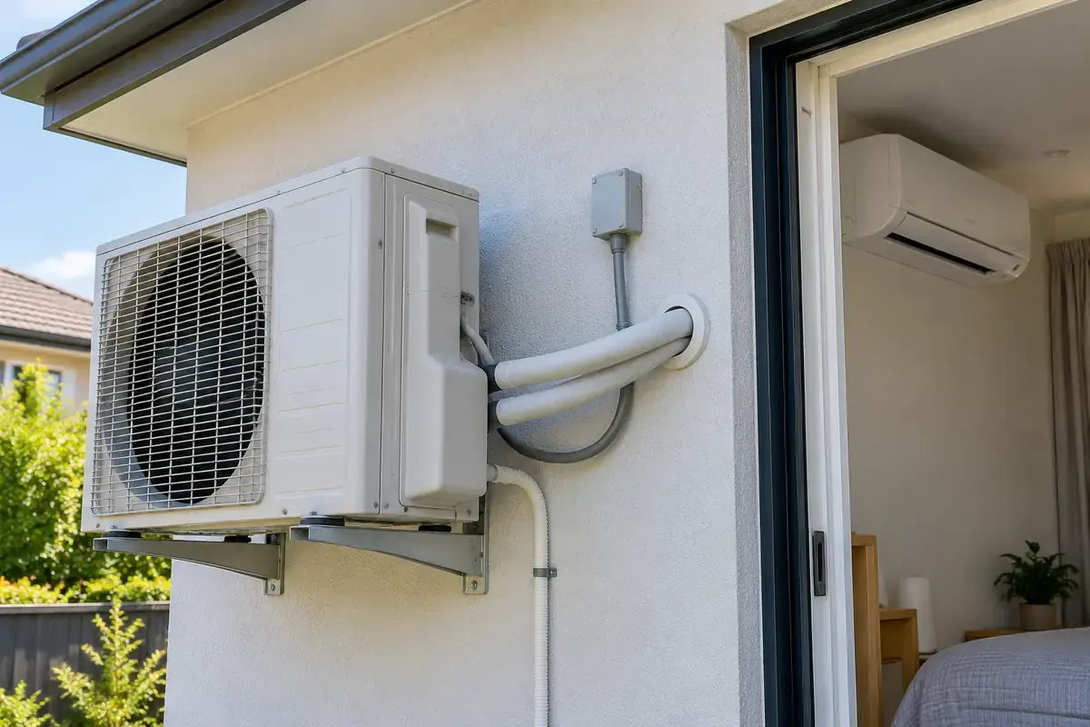
Use this table to identify the four connection routes. For a specific installation, match the indoor and outdoor model numbers to their piping and wiring diagrams. Ducted split systems may have separate air-handler wiring and drainage, while packaged and window units generally contain the refrigerant circuit in one factory-built assembly.
- Refrigerant path: Indoor coil ↔ two refrigerant tubes ↔ outdoor refrigerant circuit. The two tubes have different functions; they are not electrical cables.
- Power path: Building electrical supply → the equipment’s specified indoor or outdoor feed point, with the required protection and disconnect.
- Control path: Approved indoor and outdoor control terminals or interface ↔ matching communication/control conductors, as the model diagram requires.
- Water path: Indoor condensate outlet → a supported gravity drain, or an approved pump if needed → permitted discharge point.
Identify whether the equipment is a single-zone mini-split, multi-zone split, ducted split, or packaged unit. Then use its approved combination and installation documents to select the proper line set, wiring and drain materials.
If you are still deciding between ducted, ductless and packaged layouts, compare the main types of AC systems before finalizing the connection routes.
How Do Refrigerant Line Connections Work?
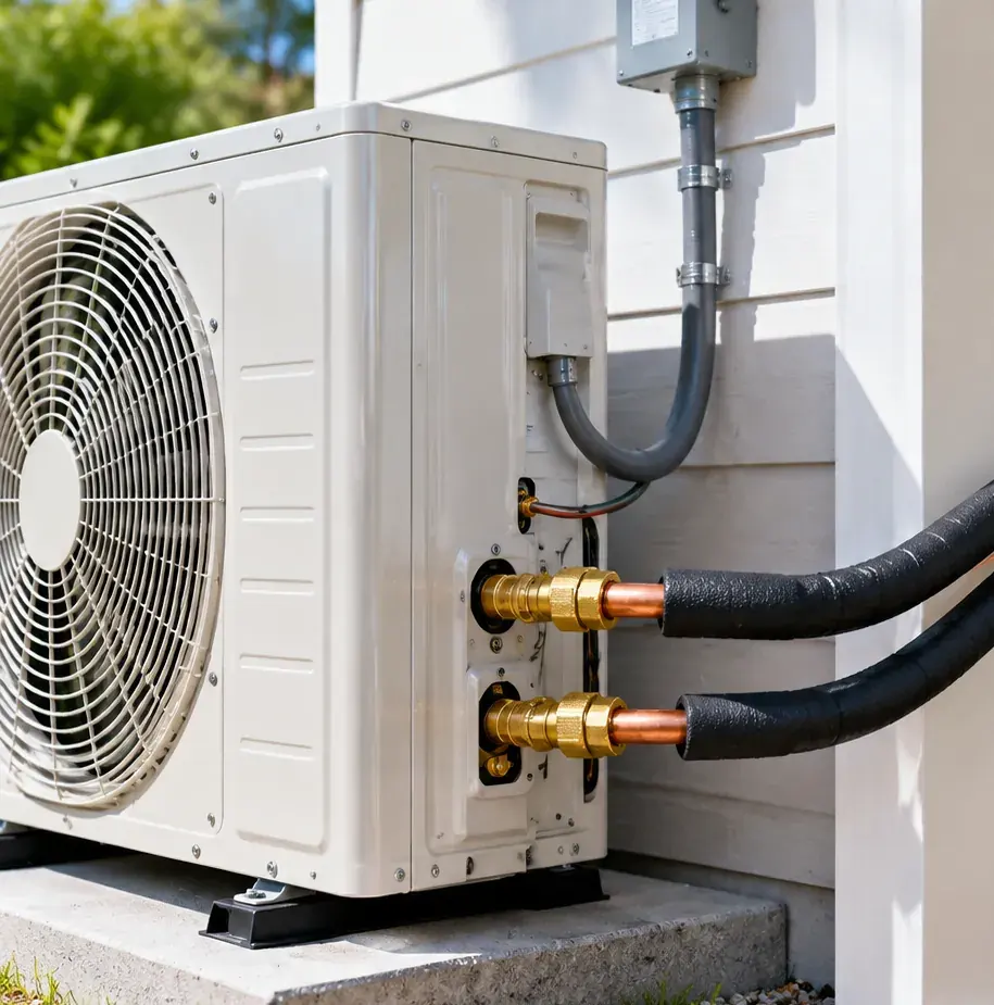
In most conventional split AC systems, two copper tubes make the refrigerant connection between the indoor and outdoor sections. The smaller tube is commonly described as the liquid line, and the larger insulated tube is commonly called the gas or suction line. Refrigerant changes state and operating conditions as it moves through the system. On heat-pump versions, flow direction and operating roles can change between modes, so the pipe labels in the actual manual matter more than a simplified cooling-only description.
Match the line set to the exact system
Choose the approved tubing diameters, material, wall thickness and insulation from the selected unit’s manual. Confirm the route length and height difference, not only the straight distance between the units. These limits affect pressure loss, oil return and the charge required for the selected configuration.
Use the sales brochure to narrow the product family, the nameplate to identify the exact equipment rating, and the installation manual to check pipe sizes, allowable length and height difference, insulation, joints and charge instructions. For a multi-zone unit, use the approved indoor/outdoor combination chart as well. Measure the proposed route on the site plan, including bends and vertical rise or drop. If the matching model document is missing, request it before ordering tubing.
A proposed line set can fit through the building yet exceed the model’s allowed length or height difference. When the route exceeds the approved limit, shorten or reroute the pipes, move the equipment, or choose a model rated for the required run. Make any refrigerant-charge adjustment only within the permitted installation range.
Keep tubing ends protected from dirt and moisture before joining. Support pipes so they do not rub against sharp masonry or electrical parts, and protect outdoor insulation from damage. Refrigerant insulation needs to prevent unwanted heat gain and condensation along the surfaces identified by the manual. The installer must also maintain any required service access and manufacturer minimum bend radius.
Complete the joints and verify the sealed circuit
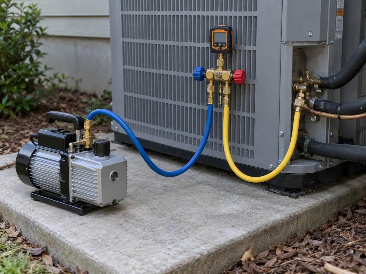
Depending on the unit and installation location, the manufacturer may specify flared connections, brazed joints, or a listed fitting type. The installer prepares each joint using the required tools and tightening method. Next come the model’s leak checks, evacuation (using a vacuum pump to remove air and moisture from newly connected open tubing), and any refrigerant-charge steps that apply to that system. A sealed, factory-pre-charged connection kit may have its own approved procedure.
A factory-charged outdoor unit does not prove that the newly installed field tubing contains no air, moisture or leaks. The commissioning record should show the applicable test method and results. If the installer discovers a leak, the joint must be corrected and the required tests repeated before the equipment is accepted.
How Do Copper Pipe Connections and Fittings Differ?
Choose a refrigerant joint approved for the AC system and installation location. Check refrigerant compatibility, the system’s operating pressure, the tubing material, temperature rating, joint location and fitting approval against the manufacturer’s specified method.
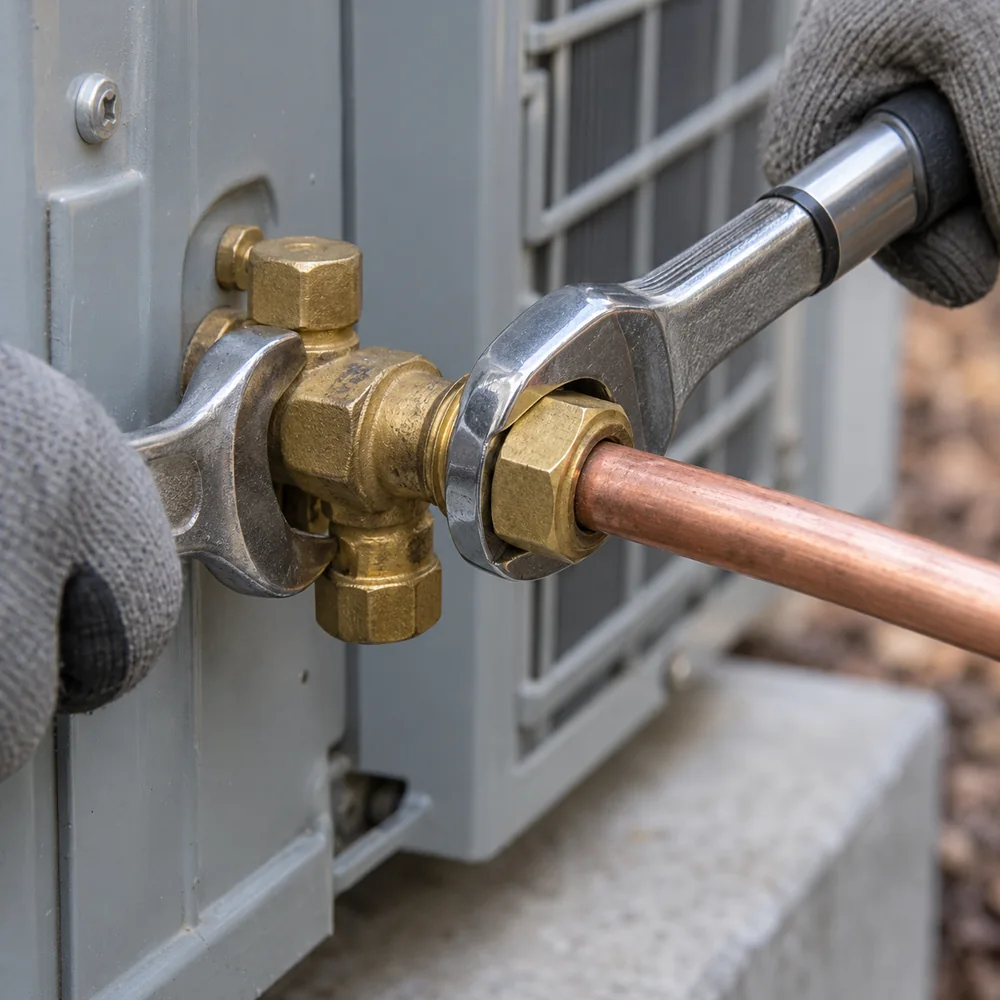
| Connection method | Common application | What to verify |
|---|---|---|
| Flare nut joint | Many conventional mini-split indoor/outdoor connections | Correct flare form, matching nut, manufacturer torque, approved location |
| Brazed joint | Many larger split-system refrigerant circuits | Approved brazing materials, nitrogen purge where required, joint accessibility and qualified work |
| Refrigeration-rated press or push fitting | Specific approved HVAC/R product and service conditions | Fitting’s refrigerant and pressure rating, tubing compatibility, tooling, listing and manufacturer approval |
| Factory-sealed pre-charged quick-connect line set | A compatible proprietary AC kit designed around those connectors | Exact indoor/outdoor kit, prescribed line set, approved length and special instructions |
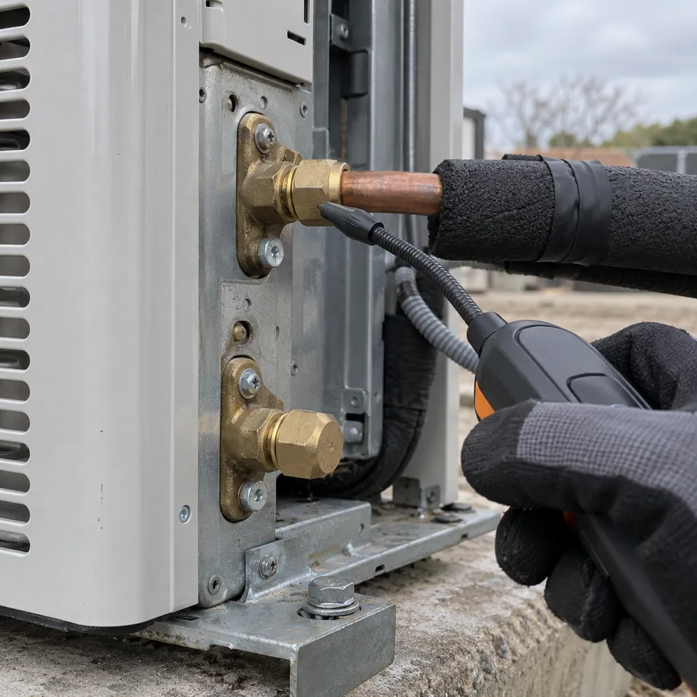
A flare joint seals a cone-shaped, widened copper tube end against a matching metal fitting. Under-tightening may let refrigerant escape; excessive force may crack or deform the joint. Use the specific model’s torque values rather than a number copied from another brand’s article. A copper pipe connection should also be insulated and supported as the manual requires.
Keep the specified flare joint where the equipment calls for it. Use brazed or refrigeration-rated press fittings only where the system and fitting instructions approve the method, materials, tools and verification steps. An A2L-rated fitting still needs to meet the full equipment and joint-location requirements; review service access and warranty requirements when selecting a different approved method.
How Are the Indoor and Outdoor AC Units Connected Electrically?
There are two electrical jobs to distinguish: supplying safe power to the equipment and linking its controls or communication signals. An outdoor-fed system receives its main supply at the outdoor unit; an indoor-fed design receives it at the indoor unit. Other models may use separate circuits. The air conditioner wiring diagram must therefore match the exact models and destination market, even when two systems have the same cooling capacity.
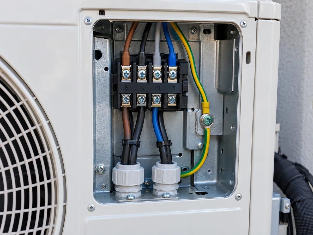
Confirm the electrical supply first
Size and protect the supply circuit from the exact model’s nameplate, electrical instructions and applicable local rules. The electrician confirms voltage, phase, frequency, required conductors and protective devices, disconnects, grounding and available building capacity. Cooling capacity in BTU/h is a performance rating; the electrical nameplate identifies what the circuit needs.
Electrical protective devices and cable requirements depend on the actual listed equipment and local rules. Before work starts, qualified personnel isolate the power and verify the circuit is de-energized. The finished supply and protective devices need inspection or testing required by the local installation rules.
Two common supply layouts:
- Outdoor-fed: The building supply enters the outdoor unit first. The indoor unit receives any required power or controls through the approved interconnection arrangement. Confirm the outdoor nameplate, supply protection and matching indoor/outdoor cable diagram.
- Indoor-fed: The building supply enters the indoor unit first. Any supply or control connection serving the outdoor unit follows that model’s wiring diagram. Confirm the indoor nameplate, protected feed, and specified outdoor interconnection.
For an outdoor-fed model, match the outdoor supply and interconnection wiring to its drawing. For an indoor-fed model, check the indoor supply and specified cable to the outdoor unit. In either arrangement, the electrician verifies each terminal function and conductor against the exact model drawing and applicable local rules.
Connect controls using their verified functions
Many mini-splits use a dedicated communication link between indoor and outdoor electronics. A conventional ducted system may instead use low-voltage thermostat terminals such as R, C, Y and G. For conventional 24V thermostat controls, our heat pump thermostat wiring guide explains common terminal functions. A communicating mini-split still needs its own approved controller diagram. Identify which control system the selected equipment uses, then match its cable type, terminal functions and communication requirements to the manufacturer’s diagram.
For multi-zone installations, follow this order: confirm the approved indoor/outdoor pairing → assign each head to its outdoor circuit or zone → verify communication cables and required addresses/settings → operate each zone and review fault codes. If one head fails, use its code and the wiring/zone records to distinguish control problems from refrigerant or other operating problems.
What should an air conditioner connection diagram show?
A useful job-specific diagram identifies the indoor and outdoor model numbers, refrigerant liquid and gas routes, equipment power feed, disconnect and protective earth, control/interconnection route, and condensate discharge. It should also show any condensate pump or third-party control interface that changes operation.
Use this connection map to plan the refrigerant, power, control and drainage routes. Attach the manufacturer’s terminal diagram for the exact equipment combination to the job drawing, and record the verified conductor functions and supply entry point before connection and startup.
Where Does the Air Conditioner Drain Connect?
The indoor cooling coil removes moisture from the air, and that water must leave through a drain. A typical wall-mounted split AC has a condensate hose that runs downhill to an approved discharge point. A ducted air handler may need a separate drain pan, trap and overflow protection depending on its design and local rules.
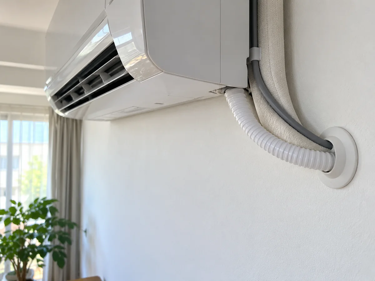
A gravity drain needs a continuous route without unwanted upward loops or low spots that trap water. If the route cannot fall enough, a compatible condensate pump may be appropriate. The pump must have the required alarm or shutdown protection and a place for service; otherwise a failed pump can let water spill into the building. Confirm water flow and any pump fault/overflow response before closing the wall opening.
Test the drain with water before closing covers or concealing the route. Check the discharge point as well as the indoor connection so water drains away from entrances, exposed walkways and other openings. When moisture appears below the indoor unit, inspect the hose and drain outlet first; then inspect insulation and, if installed, condensate-pump operation. The findings determine whether additional cooling-system tests are needed.
Can You Use Quick-Connect Air Conditioning Fittings?
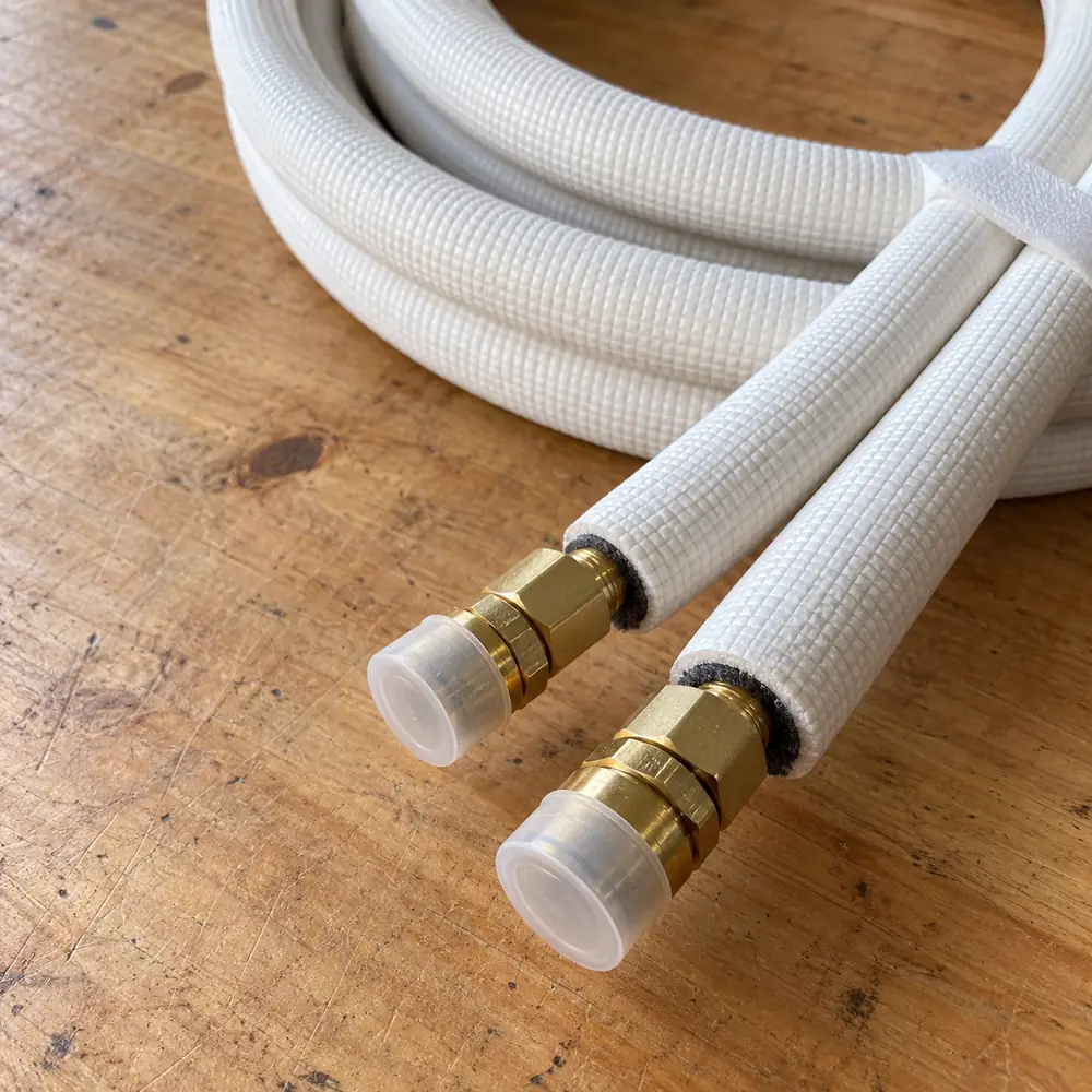
Use quick-connect fittings approved for the exact equipment and refrigerant circuit. Check the line set, connector, refrigerant and indoor/outdoor model pairing, then identify which of the four connection types you have. The table below gives the suitable documents and installation path for each.
| You have | Appropriate first check | Decision |
|---|---|---|
| Standard copper line set, field-prepared | Check the selected indoor/outdoor installation manual for a flare, braze, or approved joint. | Connect using that method; perform the required leak and evacuation steps on open field piping. |
| Factory-preflared but uncharged line set | The tube ends arrive prepared, while the uncharged field tubing remains open until installed. Confirm the specified joints and test procedure. | Join the prepared ends as specified; leak-test and evacuate the newly installed open piping under the equipment instructions. |
| Factory-sealed, pre-charged connection kit | Confirm exact equipment combination, connector design, kit length and prescribed installation procedure. | Use the matched sealed kit and its specific connection/commissioning procedure. A kit-specific no-vacuum method applies to that approved sealed arrangement. |
| Aftermarket HVAC/R-rated press or push fitting | Verify refrigerant, pressure/temperature, tube material, fitting listing, tools and equipment approval. | Install only in a system and joint location that explicitly support the fitting, using its specified tooling and required circuit tests. |
For conventional open copper piping, join, leak-test and evacuate as specified. A matched factory-sealed, pre-charged kit follows its own approved connection procedure. A factory-charged outdoor unit alone still requires the conventional open field lines to be prepared and tested under its installation instructions.
Keep factory-sealed, pre-charged lines intact and use only the couplers and equipment combinations approved for that kit. The label “DIY” does not change refrigerant-work requirements. In the United States, the EPA says Section 608 certification is required for installing or servicing mini-split refrigerant circuits when the work involves activities such as adding or removing refrigerant or connecting/disconnecting pre-charged lines. Verify the work scope and applicable requirements before proceeding. Read EPA’s Section 608 guidance.
What Should Be Verified Before and After AC Connections?
An AC connection is ready for handover when the installed models, pipe routes, electrical supply, drainage and required refrigerant checks meet the applicable instructions. Record the results, then run each intended operating mode and confirm proper operation. Use the following sequence to review the work.
- Confirm the matched equipment. Record the actual indoor and outdoor model numbers, refrigerant, capacity and whether the pair or zone combination is approved.
- Confirm the intended routes. Check permitted refrigerant pipe length and elevation, copper and insulation, wall penetrations, support and access. Include the water drain and electrical run.
- Review the electrical design. Have the responsible electrician compare nameplates with the supply circuit, protective devices, wiring diagram and required permits or inspections.
- Complete approved joints. Qualified personnel prepare and connect the refrigerant circuit using the model-specified parts and methods. Protect all open ends until work is done.
- Perform prescribed refrigerant tests. Record required pressure/leak checks, evacuation and any charge adjustment for the actual line length. Treat a failed measurement as work to fix and retest.
- Verify wiring and drainage. Complete the model-required electrical and control checks, and prove that water reaches the intended drain outlet without overflow.
- Commission every intended operating mode. Start only when prerequisites pass. Record observed temperatures, settings, supported cooling/heating operation and any fault codes. Test each indoor zone where applicable.
- Keep the handover information. Save the installation drawing, exact manuals, model and serial numbers, test results and issues that remain open.
What should the installation handover record contain?
A useful handover record identifies the equipment, installed routes, test methods, results, acceptance limits and corrected faults. Keep the measurements or test outcomes with the matching manual or drawing. When a required result is missing or fails, correct the issue and repeat the affected test before accepting the work.
| Handover item | Evidence to keep | If missing or failed |
|---|---|---|
| Matched units and instructions | Indoor/outdoor model and serial numbers; approved combination; manual or drawing revision | Confirm the pair and obtain the correct documents before commissioning |
| Installed refrigerant route | Actual tubing sizes, measured run and height difference; insulation and connection type | Correct the route or equipment selection if it exceeds the approved limits |
| Electrical supply and controls | Applicable circuit/protection checks; correct supply entry, grounding and interconnection inspection | Qualified personnel correct the discrepancy and repeat the required electrical check |
| Refrigerant circuit tests | Specified leak/pressure-test and evacuation results, and any charge adjustment, for the applicable connection method | Repair the affected circuit and repeat the manufacturer’s required test |
| Condensate drainage | Water-flow test at outlet; pump and overflow response if a pump is fitted | Correct blockage, slope or pump issue and repeat the water test |
| Startup and operating modes | Cooling/heating and individual-zone test results where applicable; settings, readings and any fault codes | Resolve the identified fault and confirm the affected mode or zone again |
If cooling passes but heating fails, record the operating mode and any fault code. Check the approved equipment pairing, control settings and manufacturer’s fault guidance; correct the cause and repeat the heating test before handover.
For the wider project sequence—from choosing equipment and mounting the units to commissioning and handover—see the full mini-split installation sequence. This connection guide focuses on the interfaces and checks between those stages.
What Do Common Air Conditioning Connection Problems Look Like?
Start with the symptom and the unit’s fault code. A communication fault points toward cables, equipment pairing and controls; water below the indoor unit points toward the drain; weak cooling calls for airflow and refrigerant-system checks. Use the actual test results to identify the cause and confirm the repair.
| What you notice | Connection to investigate | Next check and confirmation |
|---|---|---|
| Indoor head has no power | Supply or indoor–outdoor feed arrangement | Check user-accessible settings and supply status safely. Have an electrician verify the approved feed and protection; then confirm controlled startup without the original fault. |
| Indoor unit shows communication fault | Interconnection cable, model pairing or control address | Record the fault code. A technician checks model pairing, wiring and address; clear the cause and verify two-way communication and no returning code. |
| Cooling is weak after installation | Airflow, operating mode, load match or refrigerant circuit | Check filter, airflow and settings first. Compare required refrigerant test/charge records and model-specified operating readings after correction; confirm stable cooling. |
| Water drips from the indoor unit | Condensate hose, slope, pump, insulation or iced coil | Check accessible drain outlet; correct the source, run the specified water-flow test and confirm no indoor overflow. |
| Outdoor equipment trips protection | Supply/protection, fan, compressor or controls | Do not keep resetting. A qualified technician follows recorded faults, repairs the cause and completes a controlled run without a repeat trip. |
| One multi-zone head works, another fails | Approved zone pairing, connection, cable or settings | Match that head to the right zone/circuit and address, correct any mismatch, then confirm that every intended indoor zone runs without the fault. |
If the connections pass their checks but cooling is still weak, our guide to why an air conditioner is not cooling helps separate airflow, control, capacity and refrigerant-related causes.
Never open a live electrical panel or loosen a refrigerant joint just to investigate a symptom. Repeated protective trips, damaged insulation, burnt smells, or a suspected refrigerant leak warrant stopping operation and arranging competent service. After a repair, repeat the specific check that failed, then verify system operation again.
What Details Should You Confirm Before Ordering a Split AC?
For distributors, contractors and project buyers, check the connection requirements before treating two AC offers as equivalent. A split system with the required cooling capacity may still need a different power supply, pipe route, controls or installation method.
If the required cooling load or capacity is still unknown, start with the air conditioner sizing guide, then return here to compare the connection requirements of the shortlisted models.
Use the product catalog to shortlist equipment, then request the exact installation manual, approved indoor/outdoor combination sheet, wiring drawing and line-set limits. These documents let you compare connection requirements and installation scope across offers. For a proprietary quick-connect requirement, request written compatibility confirmation for the selected kit and model pair.
Browse the Airproz split air conditioner range to shortlist a product family. Then compare the exact model documentation, power supply, refrigerant, approved indoor/outdoor pairing and line-set limits for the destination market.
For an Airproz project, start with the published R32 inverter split AC product family and the Airproz HVAC FAQ to identify suitable product families and documentation questions. For the selected model, request its installation, wiring and pipe-routing documents. When a sealed quick-connect solution is required, ask Airproz to confirm whether the exact equipment supports a named kit in writing.
Project connection details to send
| Project detail | Information to send |
|---|---|
| Destination market | Country and any required local approval or documentation |
| Indoor and outdoor equipment | Exact selected model numbers, or “not selected yet” plus intended application |
| Cooling / heating duty | Load or capacity target and main room/space conditions |
| Power available | Supply voltage, phase and frequency; known circuit constraints |
| Number of zones | Number of indoor units and preliminary locations |
| Refrigerant line route | Measured or estimated route length and vertical difference, plus wall/roof constraints |
| Connection method | Standard approved tubing or a specific sealed quick-connect requirement; identify the intended kit if known |
| Order and documents | Expected quantity and requested drawings, manuals or market-specific documents |
Send the project details above with a basic plan or photos showing proposed indoor and outdoor locations. Contact Airproz with the available details, and have the local installer review the proposed connection route and electrical design for the actual site.
Conclusion
A split air conditioning connection includes two refrigerant lines, an electrical supply and control link, and a condensate drain. Match the indoor and outdoor equipment, choose the approved pipe and wiring arrangement, and complete the required electrical, refrigerant, drainage and operating checks before handover. A dedicated sealed quick-connect kit follows its own verified equipment-specific procedure.
Frequently Asked Questions
How many pipes connect a split air conditioner?
Most conventional single-zone split AC systems use two refrigerant tubes between indoor and outdoor units, usually called the liquid and gas lines. Confirm the exact sizes, connections and routing limits in the model’s manual. The condensate drain is a separate water hose or pipe, not a third refrigerant line.
Can I connect a split air conditioner using a general wiring diagram?
No. Get the wiring drawing and nameplate details for the exact indoor and outdoor models. The installer can then identify the supply entry point, communication cable and terminal functions for that equipment, rather than matching terminals by color or appearance.
Does a pre-charged air conditioner still need vacuuming?
A conventional split system with a factory-charged outdoor unit normally requires evacuation of newly installed open field lines under its instructions. A matched factory-sealed, pre-charged line-set kit may use its own approved procedure. Check which connection system is supplied, then follow the specified leak-test and commissioning steps.
Are quick-connect fittings compatible with every refrigerant?
No. Choose a fitting with approvals for the specific refrigerant, pressure and temperature range, tube material, joint location and required tools. Also confirm that the equipment manufacturer allows that connection method.
What proves the indoor and outdoor AC connection was completed correctly?
A complete handover includes the approved model pairing and drawings, recorded refrigerant and electrical checks, drainage results, and operation tests. Compare the test results with the equipment instructions, correct any failed item and repeat its check before acceptance.
Can refrigerant lines, power wiring and the drain pass through one wall opening?
Sometimes. A shared wall sleeve can be used where the equipment instructions and applicable building and electrical rules permit it. Plan the opening to maintain the required protection and separation for wiring, insulation for refrigerant pipes and a downhill drain route or approved condensate pump.