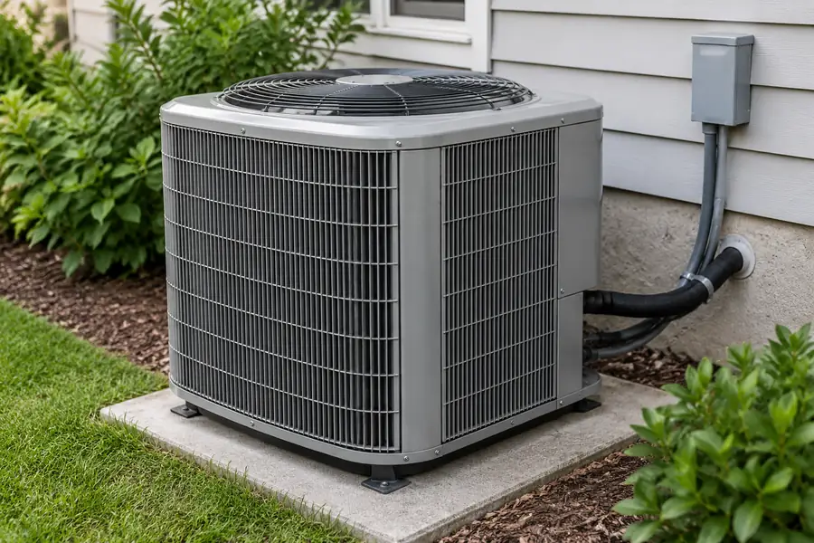
Air conditioner components explained
An air conditioner has four core cooling components: the compressor, condenser coil, expansion device and evaporator coil. A complete system also needs fans, an air filter, controls, refrigerant lines and a way to drain condensed water. In a typical split AC operating in cooling mode, the compressor and condenser are outdoors, while the evaporator and indoor fan are inside. The labeled illustration below shows their usual locations.
These four parts form the cooling circuit. Fans, controls, filters and drainage complete the system. The sections below show how each part works and where it is typically installed.

What Are the Four Main Components of an Air Conditioning System?
The compressor, condenser coil, expansion device and evaporator coil are the four core refrigeration components. Together they move heat from indoor air to the outdoors through a sealed refrigerant circuit.
| Component | Usual location | Job in simple words |
|---|---|---|
| Compressor | Outdoor unit | Raises refrigerant vapor pressure and temperature so heat can be released outside |
| Condenser coil | Outdoor unit | Releases heat to outside air as hot refrigerant vapor condenses into liquid |
| Expansion device | Model-dependent; often near the evaporator circuit | Controls refrigerant flow and lowers its pressure before indoor cooling |
| Evaporator coil | Indoor unit | Absorbs room heat while low-pressure refrigerant boils into vapor; can remove moisture |
Compressor: pressure and circulation
The compressor is usually inside the outdoor cabinet. It takes low-pressure refrigerant vapor from the suction line, squeezes it to a higher pressure and sends hotter vapor to the condenser. The condenser then removes heat from the hot refrigerant vapor, allowing it to become liquid. Rotary and scroll compressors are common designs. Fixed-speed models switch output on and off, while inverter-driven models can adjust compressor speed.
Condenser coil: heat rejection
The condenser coil is usually in the outdoor unit and releases heat to the outside air. The outdoor fan pushes or draws air across the coil. As refrigerant gives up heat at high pressure, vapor changes into liquid. A dirty coil or restricted outdoor airflow can make this work harder. If cooling performance drops, start by checking outdoor airflow and visible coil condition. The outdoor cabinet is often called the “condenser,” but the condenser coil is just one of its parts.
Expansion valve or other metering device: pressure reduction
The expansion device controls refrigerant flow and lowers its pressure before it reaches the cooling coil. This produces a colder low-pressure liquid–vapor mixture that can absorb indoor heat. Different systems use a thermostatic expansion valve (TXV), a valve that responds to refrigerant conditions, an electronic expansion valve (EEV), adjusted by a controller, or a fixed metering device such as a capillary tube. The equipment schematic shows which metering device is used and where it sits.
Evaporator coil: cooling and dehumidification
The evaporator coil sits in the indoor cooling section and takes heat from passing room air. The indoor blower moves air across it, while low-pressure refrigerant absorbs heat and boils into vapor. When the coil surface is below the air’s dew point—the temperature at which moisture in the air starts forming water—condensation collects in the drain pan. Actual coil temperature changes with airflow, room conditions, refrigerant operation and control settings.
How Do Air Conditioner Components Work Together?
The four core parts work in a repeating cycle: the evaporator absorbs indoor heat, the compressor raises refrigerant pressure, the condenser releases heat outdoors, and the expansion device lowers pressure before the cycle repeats. Indoor and outdoor fans move air across the coils.
- Evaporate: low-pressure refrigerant absorbs heat as indoor air passes over the evaporator coil.
- Compress: refrigerant vapor returns to the compressor, which raises its pressure and temperature.
- Condense: refrigerant releases heat through the outdoor coil and condenses toward liquid.
- Expand: the metering device lowers pressure and supplies the evaporator with a cold liquid–vapor mixture.
- Move air and remove water: the indoor blower delivers cooled air while the condensate system drains water removed from humid air.
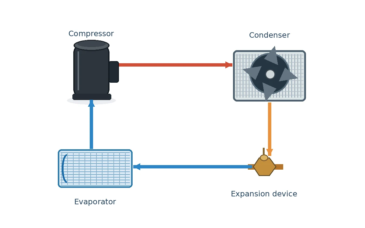
Four paths, four different jobs: Refrigerant stays inside sealed pipes and coils and moves heat between indoor and outdoor sections. Indoor air passes across the filter and cooling coil before returning to the rooms. Water collected on the cold coil flows to a separate drain. Electrical power and control signals operate the fans, compressor and other parts. These paths work together, but they are not one shared pipe.
The pressure sides are separate. The compressor raises pressure; the metering device lowers it. A reversible heat pump changes refrigerant routing between cooling and heating modes; its mode-specific schematic shows the flow path.
The same thermodynamic principles apply to many cooling-only air conditioners. Heat pumps add a reversing arrangement for heating mode, so indoor and outdoor coil roles can exchange; see our heat pump schematic and piping guide for that separate topic.
Which Components Are in the Indoor and Outdoor Units?
In a typical cooling-only split AC, the indoor unit contains the evaporator and indoor fan, while the outdoor unit contains the compressor, condenser coil, and outdoor fan. Refrigerant piping and control wiring connect the units.
| Location | Typical parts | What they do |
|---|---|---|
| Ducted indoor air handler or furnace-mounted coil | Evaporator coil, indoor blower, accessible filter, drain pan, sensors; supply and return duct connections | Cools and circulates air through ducts; removes moisture |
| Ductless indoor head | Evaporator coil, cross-flow fan, washable or replaceable filter, drain pan, sensors and louvers | Delivers cooled air directly into its room, without central distribution ducts |
| Outdoor condensing unit | Compressor, condenser coil, outdoor fan, power and protective controls | Raises refrigerant pressure and rejects heat outdoors |
| Between assemblies | Refrigerant liquid/suction lines, insulation and control/communication wiring | Connects heat-transfer and control functions; drain routing varies |
| Elsewhere in the building | Thermostat or wall controller; ducts and grilles where a ducted system is used | Requests cooling and distributes room air |
A ducted central split system usually moves air through supply and return ducts. Its evaporator may sit beside or above a furnace and use the furnace blower. A wall-mounted ductless indoor head cools its room directly. Both designs perform the same basic refrigeration functions, but their filters, fans, controls and airflow paths differ. A packaged unit places most cooling components in one cabinet.
What Do the Fans, Filters, Refrigerant Lines, and Drainage Parts Do?
The indoor fan moves air across the cooling coil and into rooms, while the outdoor fan moves outdoor air across the condenser to carry away heat. Filters catch dust before air reaches the indoor coil. Refrigerant lines connect the sealed cooling circuit, and the condensate drain removes water collected at the indoor coil.
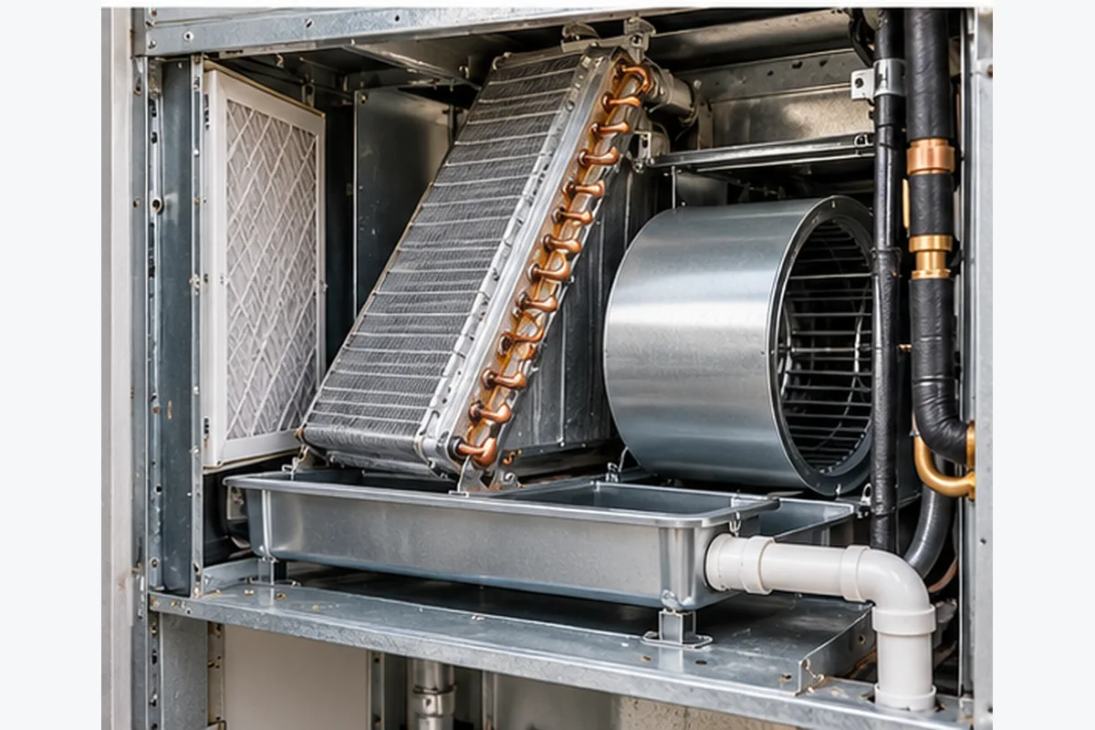
Indoor blower, outdoor fan, and air filter
The indoor blower circulates room or return air across the evaporator; the outdoor fan moves ambient air across the condenser. An air filter captures particles before they reach the indoor equipment. A clogged filter, blocked grille, dirty coil or failing fan can reduce airflow and cooling performance.
Refrigerant line set and insulation
The larger insulated suction line usually carries low-pressure refrigerant vapor toward the compressor in a cooling-only split system. The smaller liquid line typically carries high-pressure liquid toward the metering device. Pipe size, length, vertical separation, insulation and allowable routing must match the specific equipment instructions. For a replacement, confirm line size, condition, insulation and refrigerant compatibility against the new equipment specifications before reusing the line set.
Condensate pan, drain, and pump
When the evaporator removes moisture, water drops into a collection pan and leaves through a properly routed condensate drain. Some installations use a condensate pump where gravity drainage is unavailable. The drain path, slope, trap where specified, overflow protection and service access matter as much as the presence of the pan.
Where does the water go? Depending on the building, it may drain outdoors, into an approved floor drain, or through a condensate pump. If water appears near the indoor unit, have the drain, pan, pump and cold-pipe insulation checked. Water near electrical components calls for stopping the system and arranging service.
Ducts, returns, dampers, and supply outlets
In central ducted systems, return ducts bring indoor air back to the air handler while supply ducts deliver conditioned air to occupied rooms. Duct sizing, leakage, insulation, grilles and any zone dampers affect the airflow that the evaporator receives. Ductless systems do not have this central air-distribution network, but still need clear intake and discharge paths.
What Are the Main Air Conditioning Electrical Components?
The main electrical and control parts include the thermostat or room controller, sensors, control board, power-switching devices and protective controls. Many fixed-speed units use contactors and motor capacitors, while inverter systems use electronic drives to adjust compressor output.
| Electrical or control part | Function | Important design difference |
|---|---|---|
| Thermostat / room controller | Reads or receives room temperature and requests cooling | Wall thermostat on many central systems; remote or integrated control on mini-splits |
| Control PCB and sensors | Processes temperature, pressure, motor and protective inputs | Sensor types and safety logic differ by manufacturer |
| Contactor or relay | Switches selected electrical loads under control logic | Common in traditional fixed-speed systems; not universal |
| Run/start capacitor | Supports some single-phase compressor and fan motors | Not a universal component in inverter-driven systems |
| Inverter drive / power electronics | Controls variable-speed compressor operation | Requires model-specific controls and protective procedures |
| Disconnect, overcurrent and safety devices | Provide electrical isolation and protective functions | Installation requirements vary by system and jurisdiction |
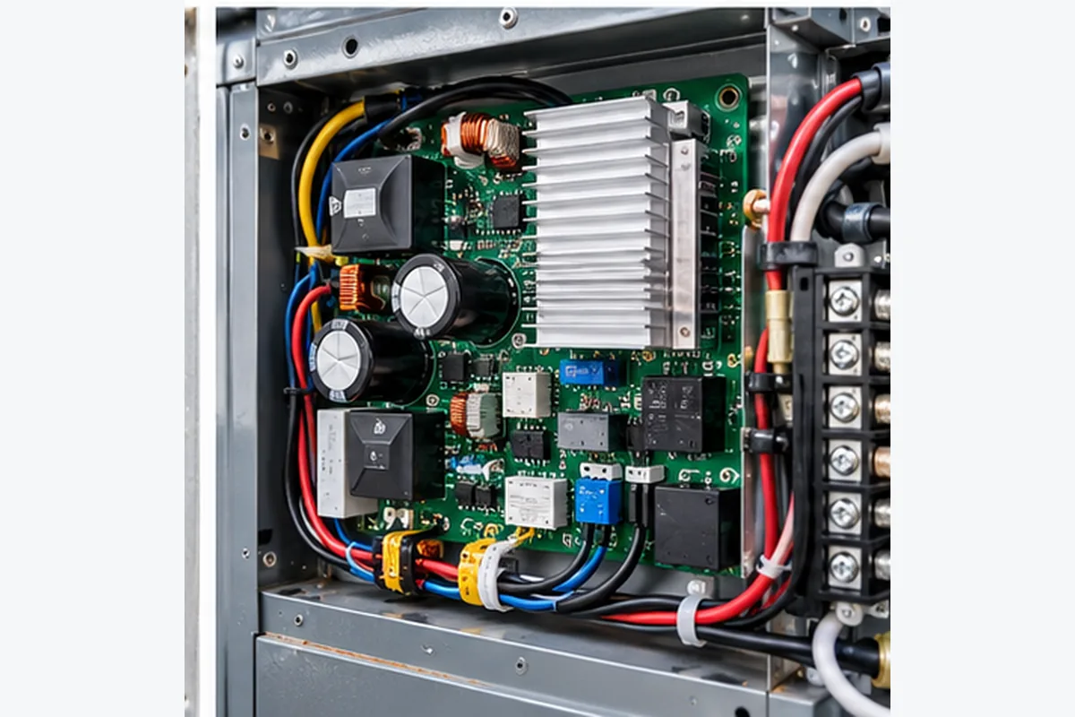
The equipment parts list identifies the exact control devices fitted to each model.
Electrical safety: Capacitors can retain a dangerous charge after power is off. Keep electrical cabinets closed; qualified technicians handle electrical testing, protective devices and refrigerant-system work.
The controls illustration explains the functions of these devices. The model’s electrical schematic provides the actual wiring connections and protective details.
How Do the Components Differ Between Split, Central, Window, and Packaged AC?
Central split AC separates the outdoor compressor and condenser from an indoor coil and blower connected to ducts. Ductless mini-split AC also has indoor and outdoor sections, but each indoor head supplies air directly to its room. Window AC contains both cooling sections in one chassis. Packaged AC places the main cooling parts in one outdoor cabinet and may deliver air through ducts.
“Central” describes how cooled air is distributed, while “split” describes the separated equipment layout. A central AC system can therefore also be a split system.
| System type | Component arrangement | How air is delivered | What to check |
|---|---|---|---|
| Central split AC | Outdoor condenser/compressor plus indoor evaporator/air handler or furnace coil | Supply and return duct system | Matched indoor/outdoor equipment, duct airflow, blower and coil compatibility |
| Ductless mini-split | Outdoor unit and one or more indoor heads | Each head supplies its served space directly | Permitted head combinations, line runs, drain routing, controls |
| Window / through-wall AC | Indoor and outdoor heat-transfer sections contained in one chassis | Directly into the room | Correct separation of indoor/outdoor air streams and installation clearances |
| Packaged / rooftop AC | All main components in one exterior cabinet | Direct or ducted distribution, depending on model | Duct connections, drainage, roof/load/access requirements |
How to recognize the layout: A ducted central split system usually has room supply and return vents, an indoor blower or furnace coil, and a separate outdoor cabinet. Ductless mini-splits use room-mounted heads to deliver air directly. Window or through-wall units put both heat-transfer sections in one chassis. Packaged equipment houses major cooling parts in one outside cabinet. Check the nameplate and model manual to confirm which system you have.
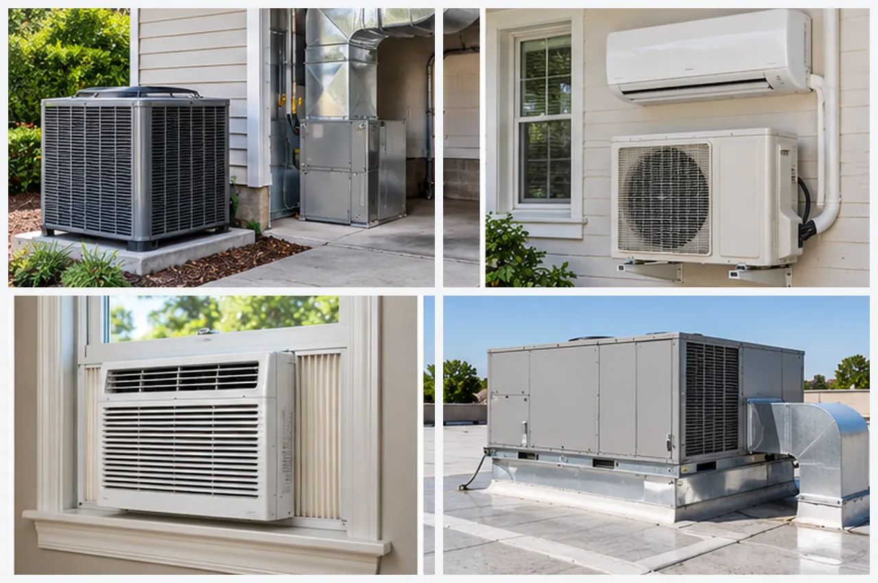
Heat pumps add reversing controls for heating. Chilled-water air handlers use a separate chilled-water supply and belong to a different system architecture. For broader system choices, see our guide to the main types of AC systems.
Which Component Might Be Responsible When an AC Is Not Cooling?
Weak airflow points first to the filter, indoor blower or ducts. If air moves but stays warm, check the cooling setting and outdoor-unit operation; the controls, coils or refrigerant circuit may need testing. Water near the indoor unit often points to the drain, pan or pump. Icing can result from airflow or refrigerant-system problems and calls for professional inspection.
First checks: Confirm cooling mode and thermostat settings. Check accessible filters and visible vents. Stop the system and call a qualified technician for icing, a burning smell, water near electrical parts or repeated breaker trips. Leave electrical cabinets and the refrigerant circuit closed.
| What you notice | What you can safely check | Possible areas | What a technician checks |
|---|---|---|---|
| Weak supply airflow | Inspect the accessible filter and visible supply and return grilles | Filter, room openings, blower, coil or ducts | Blower performance, duct static pressure and coil condition |
| Air moves but is not cold | Confirm cooling mode and setpoint; note outdoor fan activity from a safe viewing position | Controls, outside unit, refrigerant circuit, heat-transfer surfaces or cooling load | Airflow, controls and refrigerant-side performance at relevant conditions |
| Ice on indoor coil or line | Stop cooling; do not scrape or chip away ice | Low airflow, refrigerant-flow problem or controls | Airflow and refrigerant circuit after safe thawing |
| Water near indoor unit | Stop cooling if water threatens electrical equipment or property | Drain, pan, pump, overflow control or insulation | Drain routing, blockage, insulation and condensate safety switches |
| Outdoor section does not run | Review thermostat settings. For repeated breaker trips, stop the system and arrange service | Power, thermostat request, safety controls, fan, drive or compressor | Electrical supply, protections, motor and controls |
What to tell the technician: your exact model number, when the problem started, the operating mode and setpoint, any error code, and whether you noticed ice, water, unusual noise or a smell.
For a fuller troubleshooting path, use our air conditioner not cooling guide. A technician can combine these observations with airflow, electrical and refrigerant-system measurements to find the cause and recommend the appropriate repair.
What Should You Check When Comparing AC Units or Replacement Components?
Before choosing an AC system or replacement component, check six things: the exact model and approved equipment pairing; cooling capacity at the design conditions; refrigerant and line-set requirements; electrical and control compatibility; airflow and condensate drainage; and available OEM service or replacement-part documentation.
| Before you approve | Request this evidence | Decision rule |
|---|---|---|
| Indoor/outdoor compatibility | Exact model numbers and manufacturer-approved pairing | Use a manufacturer-listed indoor/outdoor pairing for the intended configuration |
| Cooling output at your conditions | OEM performance data for project indoor and outdoor design conditions | Compare published capacity at the project design conditions with the calculated cooling load |
| Refrigerant and piping | Model refrigerant specification, line size, length, elevation and safety instructions | Check the permitted refrigerant, line length, height difference and local installation rules |
| Electrical supply and controls | Nameplate voltage/frequency, control compatibility, protection and installation documents | Match rated voltage, frequency, protection and controller connections to the installation |
| Airflow and condensate | Duct/fan data where applicable; filter, drain and service access | Verify duct or fan airflow, drain route, overflow protection and maintenance access |
| Service and spare parts | Parts references, maintenance instructions and clearances | Match the OEM part reference or approved alternative to the exact equipment model |
For replacement parts, compare the equipment nameplate with the OEM parts list and approved alternatives. Confirm refrigerant, electrical and dimensional specifications before ordering.
The U.S. DOE Building America air-conditioning guide explains matched equipment and installation considerations. In the United States, technicians servicing refrigerant systems must also follow applicable EPA Section 608 refrigerant-management requirements. For projects outside the United States, follow the refrigerant-handling and installation rules of the destination market.
Comparing AC equipment for a project? Share your destination market, design conditions, target cooling capacity, power supply, preferred system layout and any shortlisted model numbers. Review the AirProz air conditioner product range and request the technical documents available for your intended configuration.
Frequently Asked Questions About Air Conditioner Components
What are the four major components of an air conditioning system?
The four core refrigeration components are the compressor, condenser coil, expansion device and evaporator coil. Fans, controls and other supporting parts are also necessary for a working installation.
Why do some guides list four AC components and others list five or more?
Four usually refers to the core refrigerant-circuit components. A list of five or more may count fans, the thermostat, controls or other supporting parts. The difference is generally what the list includes, not a disagreement about the refrigeration process.
Is the outdoor AC unit the condenser or the compressor?
The outdoor cabinet on a typical split AC contains both the compressor and condenser coil, plus an outdoor fan and controls. People sometimes call the entire outdoor cabinet the “condenser,” but the condenser coil is only one part inside it.
Where is the expansion valve in a split air conditioner?
In a split AC, the expansion device may sit near the indoor evaporator or inside the outdoor unit, depending on the design. Use the equipment schematic to locate it in your model.
Do all air conditioners have capacitors and contactors?
No. Many conventional single-phase, fixed-speed units use motor capacitors and contactors. Inverter-driven units may use different power electronics and switching arrangements.
Are central air conditioning components different from mini-split components?
Central ducted AC uses a central blower and ducts to distribute cooled air. Ductless mini-splits use one or more indoor heads to cool rooms directly. Both perform the same four core refrigeration functions.
Can I use a generic air conditioner components diagram for wiring or replacement parts?
No. A general component diagram identifies parts and explains cooling; wiring and part replacement require the exact model’s wiring diagram and OEM parts list. Qualified technicians handle electrical and refrigerant work.
Can a symptom tell me which AC component to replace?
A symptom tells you where to investigate first, not which part to order. Weak airflow can start with the filter or blower; water leakage often starts with the drain. A technician checks the relevant system measurements before choosing the repair.
Understanding Air Conditioner Components: The Key Takeaway
An air conditioner cools by moving heat through four core refrigeration components: the evaporator absorbs indoor heat, the compressor raises refrigerant pressure, the condenser releases heat outdoors, and the expansion device lowers pressure to start the cycle again. Fans, filters, controls, refrigerant lines and drainage support that cooling process.
Knowing each part’s location and job helps you describe a problem and compare system layouts. For an installation or replacement, match the actual model numbers, approved equipment pairing and published performance to the project’s conditions.