A heat pump schematic diagram shows how components relate and how a system works. To read it, identify the drawing’s purpose, check its legend and operating state—the mode and any valve or switch condition shown on the drawing—then follow the relevant connections. Before using the information for a specific unit, confirm that the drawing matches its model, controls and configuration.
Quick answer: Start with the question you need to answer. Use a refrigeration schematic to follow how the heat pump moves heat, a hydronic or piping diagram to follow the water system, and a wiring or control drawing to understand electrical connections. If you are checking a specific heat pump, make sure the model, drawing revision, controller and configuration match before using the diagram.
Which Heat Pump Drawing Do You Need?
If you want to understand the cycle, start with a refrigeration schematic. If you need to understand water-side connections, use a piping diagram. For electrical connections or site dimensions, find the appropriate wiring or installation documents.
Decision rule: Choose the drawing by the question. Use a refrigeration schematic for the heat-transfer cycle, a piping diagram for the water system, a wiring or control drawing for electrical relationships, and an installation drawing for physical locations, clearances and interfaces. For a specific heat pump, verify the model and document revision before applying the drawing.
| Drawing type | It can help you understand | It does not prove by itself |
|---|---|---|
| Refrigeration schematic | Refrigerant path, the four main cycle functions, and how component roles change with the stated operating mode | Project capacity, pipe size, refrigerant charge, physical routing or installation approval |
| Hydronic or piping diagram | Water-side paths, pumps, tanks, branches and the heat-exchanger connection between the heat pump and water system | Required flow, final tank size, freeze-protection suitability or final system design |
| Wiring or control drawing | Power connections, control signals, terminals, component references and cross-sheet relationships | Exact terminal use, voltage, protective devices or controller compatibility unless the document matches the model and configuration |
| Installation drawing | Physical locations, connections, dimensions, clearances and service interfaces shown in that document | Capacity, efficiency, complete control logic or approval for a different model or project |
Scope rule: The drawing type tells you what question it can answer. The model, configuration and revision tell you whether that answer applies to your heat pump.
Refrigerant is the fluid that carries heat in the refrigeration circuit. Hydronic means a system that carries heat using water or a water-based fluid. Drawing names can overlap: one document may contain several diagram types. Check the information shown, rather than relying on its title alone.
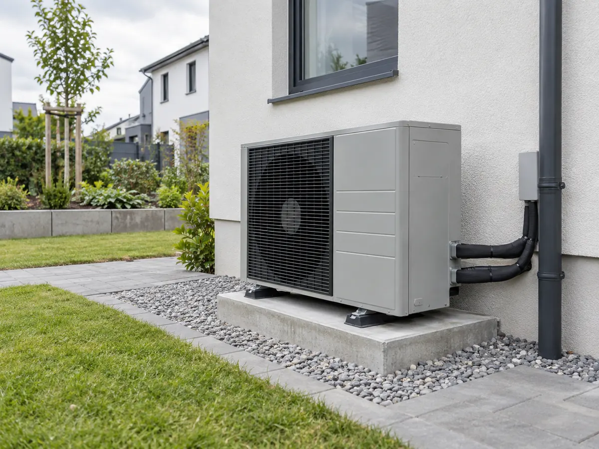
Also identify the system’s scope. An air-to-air heat pump delivers heating or cooling to air; an air-to-water system serves a water circuit. Ground-source and water-source labels describe the heat source, so check the load side separately. A generic heat pump diagram does not represent every arrangement.
How to Read a Heat Pump Schematic Step by Step
Use this sequence on the drawing in front of you:
- Check what the drawing is for and which document you have. Read the title, drawing number, revision and the equipment it covers.
- Read the legend and labels. Establish what the symbols and lines represent: refrigerant, water, electrical connections or other relationships.
- Confirm the operating state. Check whether the drawing shows heating, cooling or another stated condition. Read any valve or switch-state notes.
- Follow one relevant path. Start at a labelled component or interface. Follow its connections, confirm junctions and continue through any sheet references. Explain what each connected component does along that path.
- Mark what remains unconfirmed. If a symbol, connection or reference is unclear, identify the missing information. Check the model and configuration before applying the interpretation to equipment.
At the end, you should be able to explain the path’s starting point, connected components and destination—or point to the exact place where more information is needed.
Stop and Verify Before You Continue
| If you find | Why it matters | What to do next |
|---|---|---|
| No legend or an unclear symbol | You cannot confirm what the line, symbol or marking means in this document. | Find the legend, note or matching document before tracing the path further. |
| The operating mode is not identified | Heat-exchanger roles, valve positions or control states may change between heating, cooling, defrost or another condition. | Confirm the stated operating condition before assigning component roles. |
| A cross-sheet reference is missing or unresolved | The connection may continue elsewhere, so the path is incomplete. | Find the referenced sheet or document instead of assuming that the path ends. |
| The model, controller or revision does not match | The relationship may belong to another equipment configuration. | Stop using the diagram to make a decision about a specific heat pump model until you find the matching document. |
Read the Legend, Labels and Operating State
The legend is the drawing’s key. It defines how that particular document uses symbols, line styles and markings.

| What you see on the drawing | What to check first |
|---|---|
| Component symbol | Its legend description and identifying label |
| Line colour or style | Whether it denotes a fluid, conductor, signal, grouping or another relationship |
| Line or terminal label | The identity assigned in this document and any referenced explanation |
| Junction or crossing | How the drawing distinguishes a connection from a crossing |
| Arrow | Whether it indicates fluid flow, heat transfer or another direction |
| Sheet or component reference | The matching page, drawing or component description |
Do not assume that red means hot water, blue means cold water or every dashed line represents a wire. For example, a dashed line can indicate a mechanical relationship. The meaning must come from the drawing’s own conventions.
Check the mode label and any stated valve or switch conditions before tracing. A heating-mode path should not be assumed to describe cooling or defrost; when the state is not identified, limit your explanation to the connections actually shown and seek the relevant mode documentation.
The DOE’s archived engineering drawings handbook explains the role of legends, notes and drawing types. It is a fundamentals reference, rather than a current heat-pump installation standard.
Follow Connections and References Across Sheets
Read connectivity rather than page layout. Two lines crossing on paper do not, by themselves, establish a connection. If the legend defines a marked junction, use that definition; if the crossing is ambiguous, do not complete the path by guessing.
As a reading example, suppose a labelled path ends at a reference to another sheet. Find the matching reference there, check that it identifies the same connection, then continue. The line reaching the edge of the first page does not mean the physical circuit ends there.
A schematic may arrange components to make their function easier to understand. Their position or line length on the page does not establish their installed location or pipe length. Likewise, a switch state shown on paper is not proof that the equipment’s power has been safely isolated on site.
Follow the Refrigerant Circuit in Heating and Cooling
For a conventional heat pump cycle in which the refrigerant evaporates and condenses, follow these four main steps. Check the operating mode before deciding what each heat exchanger is doing.
The operating mode changes what the components are doing. A component label can stay the same even when its job changes. In a reversible heat pump, the same heat exchanger can release heat in one mode and absorb heat in another. Do not use a heating-mode explanation for cooling or defrost unless the drawing clearly shows that condition.

Follow the Four Main Steps of the Refrigeration Cycle
| Function | What happens | What to identify on the diagram |
|---|---|---|
| Evaporation | Refrigerant absorbs heat at a heat exchanger | The heat-source side in the stated mode |
| Compression | The compressor raises refrigerant vapour pressure | Compressor inlet and discharge connections |
| Condensation | Refrigerant releases heat at a heat exchanger | The heat-delivery side in that mode |
| Expansion | An expansion device reduces refrigerant pressure | The connection leading back toward evaporation |
In a simplified heating-cycle drawing, start at the compressor discharge and follow the path to the heat exchanger releasing heat. Continue through the expansion device to the heat exchanger absorbing heat, then back to the compressor inlet. If extra branches or valves are shown, follow that drawing’s labels and stated mode.
These are four functions, not an inventory of every valve, sensor or other component. Use the actual drawing’s labels to identify additional equipment.
Recheck the Path When the Mode Changes
In a conventional reversible air-source heat pump, changing from heating to cooling swaps the heat exchangers’ evaporator and condenser roles. The reversing valve routes compressor discharge to the heat exchanger releasing heat in the selected mode.
| Shown mode | Outdoor heat exchanger | Building-side heat exchanger |
|---|---|---|
| Space heating | Absorbs heat: evaporator role | Releases heat: condenser role |
| Space cooling | Releases heat: condenser role | Absorbs heat: evaporator role |
“Outdoor coil” does not mean “evaporator.” Cooling capability and valve electrical logic are model-specific; use the applicable model documentation before assigning valve logic or control behaviour.
Defrost is another operating condition. A heating diagram alone does not explain the complete defrost sequence; use the matching control documentation. For a fuller air-to-water explanation, see how an air-to-water heat pump works.
What to remember: A refrigeration schematic can show the refrigerant path and the main component roles for the stated operating mode. It cannot by itself prove pipe size, refrigerant charge, project capacity or that the drawing is approved for installation.
Read an Air-to-Water Heat Pump Piping Diagram
On an air-to-water heat pump schematic, separate the refrigerant circuit from the water-side circuit. Then locate the unit interfaces and follow the pumps, tanks and distribution branches shown.
Separate the Refrigerant and Water Loops
The refrigerant and water-side fluid transfer heat through a heat exchanger; they do not become one fluid circuit. Check both sides of that boundary independently.
On the water side, trace the labelled outlet toward the connected load and follow its return path. Use the drawing’s arrows and component labels to establish direction. Do not assume that the supply is always the upper line or that left-to-right layout represents flow.
Confirm whether the water-side fluid is water or a specified antifreeze mixture. For more detailed component and layout interpretation, use our air-to-water heat pump diagram guide.
Monobloc vs Split Heat Pumps: Where the System Connects to the Building
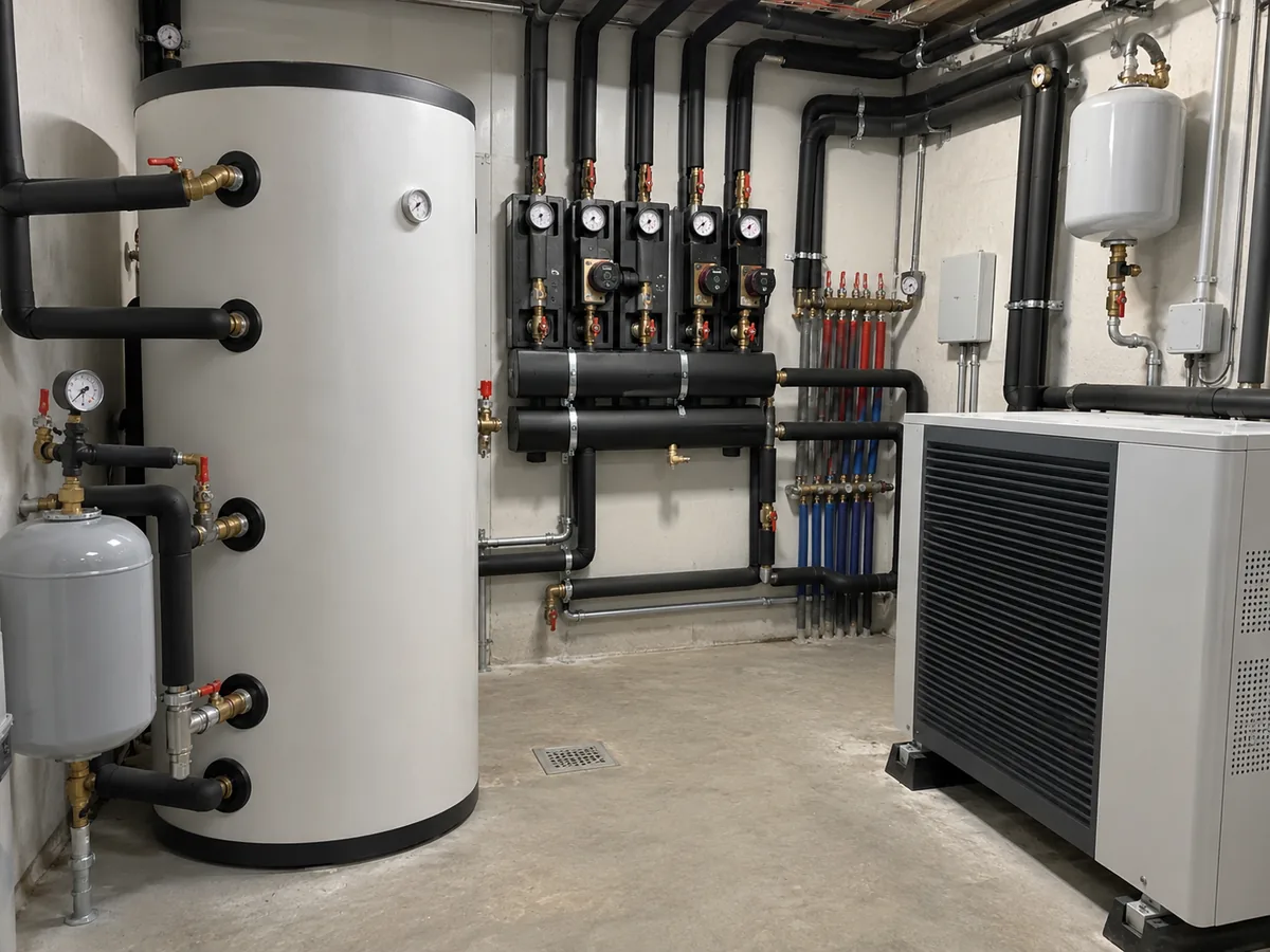
The interface between outdoor and indoor equipment helps explain what the connecting lines carry.
| System type | What to look for |
|---|---|
| Monobloc air-to-water heat pump | Refrigeration components grouped in the outdoor unit, with water-side connections toward the building |
| Refrigerant split air-to-water heat pump, where field refrigerant lines connect the outdoor and indoor sections | Refrigerant connections between outdoor equipment and an indoor water-side heat exchanger |
This comparison covers conventional refrigerant split arrangements. A product name containing “split” is not sufficient to identify the connection medium: check the actual interface labels and model documents. Caleffi’s configuration guide illustrates these conventional layouts and outdoor water-side protection considerations.
Example: Outdoor Water Circuit During Freezing Weather and Power Loss
Condition: Outdoor water-filled pipework is exposed to subfreezing conditions while electrical power is unavailable.
What changes: A pump, heater or active control can no longer be assumed to provide freeze protection.
Why: Those protective functions depend on electrical power.
Check: Verify the actual water-side arrangement, freeze-protection method, fluid condition and applicable manufacturer instructions.
Action: Do not treat the presence of a pump or heater on the schematic as proof that the outdoor section remains protected during a power outage. Have a qualified professional verify the manufacturer’s permitted freeze-protection arrangement for the site.
Follow the Water Path Through Pumps, Tanks and Branches
For each pump, ask which connected circuit it serves. For each branch, find where it leaves the main path and where it returns. If valves or multiple pumps are shown, check their relationship to the stated operating condition before assuming that every branch carries flow at the same time.
A buffer tank provides extra fluid volume for thermal storage in a heating or cooling circuit. A domestic hot water (DHW) cylinder serves hot water for taps and showers. Both may look like tanks on a schematic, but their fluid connections and purposes differ. Check the labels and any internal heat-exchange boundary before treating them as interchangeable.
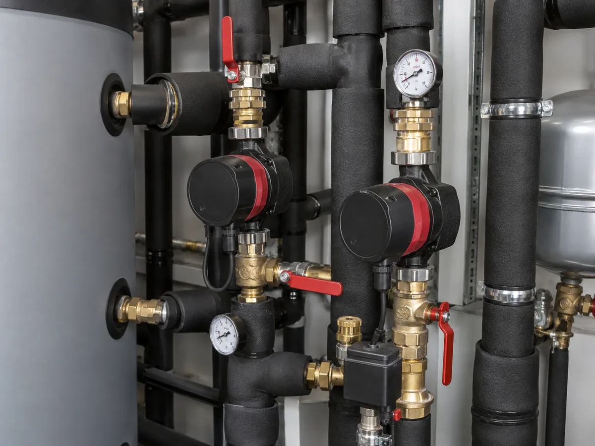
Different water-system arrangements can use different tank connections or omit a separate buffer tank under particular conditions. Caleffi’s system examples demonstrate that variety. They do not establish whether your heat pump needs a tank: the unit’s requirements, available system water volume—the amount of system water that remains connected to the heat pump in that operating condition—zoning and controls must be checked separately.
When valves close some branches, the water volume available to the heat pump and the active flow paths can change, depending on the piping arrangement. Compare that operating state with the unit’s flow and water-volume requirements; a layout drawn with every branch open does not establish suitability in other states.
When reading a direct path, a tank inserted into that path or separate heat-source and load branches, focus on which components share the path and where branches reconnect. The diagram explains the arrangement; it does not independently establish suitable flow rates, tank volume or pipe sizes.
What to remember: A hydronic diagram can show the water-side path, pumps, tanks and branches. It cannot by itself prove the required flow, tank volume, pipe size or whether the freeze-protection arrangement is suitable for your unit and site.
Read Heat Pump Wiring and Control Drawings
A heat pump wiring diagram shows electrical connections; a control schematic shows how control signals and components work together. One document may include both. Find the labelled connection points, called terminals, then use the labels and references to tell power connections from control signals.
How to Tell Power Lines from Control Signals
On the page, locate the incoming supply identification and the components it serves. Separately identify the controller, sensors, operating requests such as a heating or cooling demand signal, and referenced interfaces shown. Use the legend to establish which lines represent conductors and which represent another relationship.
The same component can appear in more than one part of a schematic. For example, an electrically operated switch—a relay—and its contacts may be linked by identifying labels rather than being drawn together. Follow the document’s component references; proximity on the page is not the test of association.
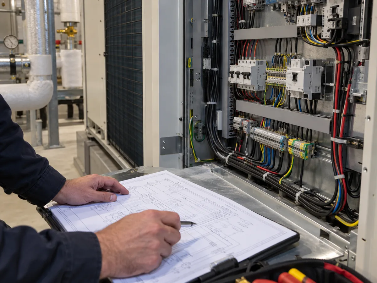
Do not infer voltage, terminal function or controller compatibility—whether the controller and the selected heat-pump configuration are designed to work together—from line colour. Symbols may show devices in a stated normal or de-energized (unpowered) condition, but that convention does not establish the live condition of the equipment.
Stop Before Applying the Wiring Diagram If…
- the terminal labels do not match the equipment;
- the controller or installed accessory differs from the drawing; or
- the document revision cannot be confirmed.
In those cases, find the matching model documentation instead of inferring wiring from line colour, physical terminal position or a similar-looking unit.
Match Labels and References to the Correct Document
When a connection points to a controller diagram, accessory instruction or another sheet, read that document before explaining the complete relationship. A clear line on one page cannot supply the missing meaning of an undefined terminal on another.
If two units belong to the same product family but have different power supplies, controllers or options, their connection documents may differ. Confirm the applicable configuration rather than copying a neighbouring model’s diagram.
For a separate guide to conventional thermostat connections, see heat pump thermostat wiring guide. The exact heat pump and thermostat instructions still control applicability. For physical wiring or commissioning, use qualified professionals following the relevant manufacturer instructions and local requirements; the DOE’s heat-pump training material explains that professional installation boundary.
What to remember: A wiring or control drawing can show electrical and control relationships. Exact terminal assignments, voltage, protective devices and controller compatibility must come from the matching model documentation.
Check That the Drawing Matches Your Heat Pump
A clear-looking diagram is not necessarily the right diagram for your heat pump. Match the equipment and document first, then check whether the drawing answers your question.
Three Checks Before You Trust the Drawing
- Right drawing type: Does this drawing answer the question you are trying to solve?
- Right equipment: Does the model, controller and installed configuration match the document?
- Right document version: Is the drawing number and revision the one that applies to that equipment?
If any one of these checks fails, use the drawing only for general understanding until the correct document is found.
Match the Model, Revision, Controller and Options
When you ask us about a specific Airproz heat pump, we first match the model and drawing revision before using the diagram to answer your question.
| Check | What to confirm |
|---|---|
| Equipment model | The model or product identifier is covered by the document |
| Drawing number and revision | The drawing number and revision match the instructions you are using. Do not assume another revision is the same. |
| Controller and accessories | The named controls and installed options are covered |
| Configuration and operating mode | The diagram represents the relevant arrangement and state |
| Referenced information | Required sheets, legends and associated instructions are available and consistent |
| Intended use | The document provides the detail needed for the question you are answering |
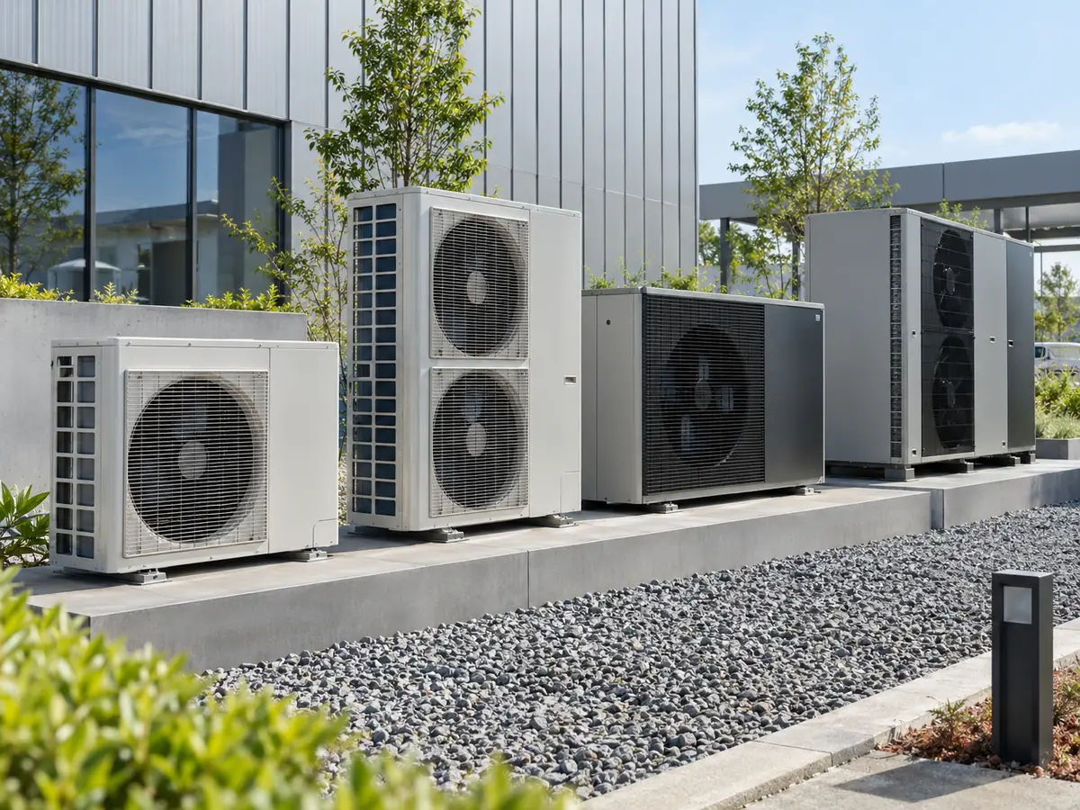
Similar-looking diagrams can still belong to different models, controllers or revisions. Terminal assignments, accessories and operating logic may also differ. Use visual similarity to understand the system concept—not to confirm that the document applies to your heat pump.
What Happens If You Use the Wrong Drawing?
The main risk is not that one diagram looks different from another. It is using a drawing to answer a question, model or revision it was never meant to cover.
| Common mistake | What can go wrong | Better check |
|---|---|---|
| “The refrigeration schematic shows the route, so I can use it as an installation drawing.” | Pipe routes, dimensions, clearances or equipment positions may be assumed incorrectly. | Use the applicable installation drawing and project layout for physical locations and dimensions. |
| “The wiring looks similar, so it should match my unit.” | Terminal, protection or control relationships may belong to another model, controller or option set. | Match the model, controller, drawing number and revision before applying the wiring. |
| “A pump or heater is shown, so freeze protection is covered.” | An active protection method may not work during a power loss, and the shown arrangement may not match the installed system. | Check the actual freeze-protection method, fluid condition, power-loss condition and manufacturer instructions. |
| “The schematic shows the system, so it proves capacity or efficiency.” | The drawing does not establish performance at your project operating conditions. | Use model-specific technical data with the stated operating and test conditions. |
| “An older revision is close enough.” | Controller, accessory or connection details may have changed. | Use the current applicable revision for the equipment being checked. |
If a check remains unresolved, name the missing information. You may still use the drawing to understand the general principle, but not to confirm the equipment-specific answer.
What to remember: Similar-looking or readable drawings are useful for general understanding, but model-specific decisions still require the matching equipment and document revision.
Know When Another Drawing or a Professional Is Needed
A schematic can show a correct relationship without supplying the information needed to size, install or approve it.
| If you need to know | What to use instead of guessing from the schematic |
|---|---|
| Installed dimensions, routes or clearances | Applicable manufacturer installation documents and project drawings |
| Capacity or efficiency | Model-specific technical data with its stated operating and test conditions |
| Pipe size, flow or tank volume | Applicable unit requirements and system design information |
| Cable, electrical protection or terminal connections | Matching electrical instructions and the relevant professional design/installation requirements |
| Confirmation of the installed configuration | Project and equipment documentation checked by the responsible professional |
An efficiency figure such as coefficient of performance (COP)—heating output relative to electrical input at stated conditions—cannot be inferred from the arrangement of lines and components. Neither can a schematic alone prove available capacity at your project’s operating conditions.
For site planning and commissioning considerations, use our air-source heat pump installation guide. Actual installation, electrical connections and refrigerant work need the applicable documents and appropriately qualified personnel.
Need Help Checking a Heat Pump Drawing?
If you are checking one of our space-heating heat pumps, you do not need to prepare a full RFQ just to clarify a document question. Start with the equipment identity and the specific connection or drawing issue you want to check.
| Send Airproz | Why it helps |
|---|---|
| Heat pump model or product identifier | Helps identify which model document should be checked. |
| Connection or specific question | Helps show whether you need a refrigeration, water-system, wiring, control or installation document. |
| Drawing number or revision, if available | Helps distinguish between document versions. If you do not have the drawing number or revision, send the model and your question first. |
We use these details to identify which document should be checked next and what information remains unresolved. The first outcome is document direction and a clear list of remaining checks—not automatic model approval, engineering sign-off or installation verification. Ask Airproz about a heat pump drawing.