Quick answer: HVAC expansion and metering devices can be grouped into seven practical types: manual expansion valve, capillary tube, fixed orifice/piston, automatic expansion valve (AEV), thermostatic expansion valve (TXV/TEV), float valve, and electronic expansion valve (EEV/EXV).
For most modern direct-expansion (DX) HVAC comparisons, start with fixed restriction vs TXV vs EEV:
- Fixed restriction: simplest; it can work well when the complete refrigerant circuit is factory-matched around a relatively narrow operating range.
- TXV: mechanically changes refrigerant feed in response to evaporator-outlet superheat.
- EEV: electronically changes valve position using a controller and pressure/temperature sensor inputs.
There is no universal “best” expansion valve. The right direction changes with load range, compressor behavior, refrigerant circuit, operating conditions, flow direction, and the control method the system actually needs.
The 5 checks that change the answer
| Check | Why it changes the choice |
|---|---|
| Load range | A fixed opening and an actively controlled valve respond differently when evaporator load changes. |
| Compressor behavior | A compressor that speeds up and slows down across a broad range can increase the value of active refrigerant-flow control. |
| Refrigerant circuit | Device capacity and arrangement must match the actual refrigerant and circuit, not only the unit’s nominal capacity. |
| Flow direction | Reversible heat pumps may use separate metering paths, check-valve bypasses, bidirectional devices, or another model-specific arrangement. |
| Control target | Fixed restriction, evaporator pressure, outlet superheat, liquid level, and electronic control solve different control problems. |
If these five conditions are not known, stop at device-family direction rather than confirming an exact component.
1. 7 Types of Expansion Valves and Metering Devices at a Glance
Seven practical groups are manual expansion valves, capillary tubes, fixed-orifice or piston devices, automatic expansion valves, thermostatic expansion valves, float valves, and electronic expansion valves. The useful distinction is not just the name of each device, but what controls refrigerant flow and how the device responds when the system condition changes.
Do not compare these devices only by name. The fastest way to understand them is to ask what actually controls refrigerant flow: a fixed restriction, evaporator pressure, outlet superheat, liquid level, or an electronic controller using sensor inputs.
| Type | What controls refrigerant flow? | Best first-fit condition | Main limitation |
|---|---|---|---|
| Manual expansion valve | Hand-adjusted valve position | Special systems with stable or manually managed operation | Does not follow load automatically |
| Capillary tube | Fixed tube diameter and length | Small factory-matched systems | Strongly tied to the matched circuit and charge |
| Fixed orifice / piston | Fixed opening | Factory-matched systems with a relatively narrow design range | Cannot actively change opening as load changes |
| Automatic expansion valve (AEV) | Evaporator pressure | Applications with relatively stable evaporator loading | Not the same control objective as TXV superheat control |
| TXV / TEV | Evaporator-outlet superheat | DX systems with changing evaporator load | Must be selected for refrigerant and real operating conditions |
| Float valve | Refrigerant liquid level | Flooded refrigeration arrangements | Not a normal DX superheat-control device |
| EEV / EXV | Controller using sensor inputs | Broad operating range or electronically controlled systems | Valve, controller, sensors, wiring and logic must work together |
A TXV and an AEV can both change their opening, but they react to different system variables. A capillary tube and a fixed-orifice piston are both fixed metering devices, but they are not physically the same component. A float valve controls liquid level rather than evaporator-outlet superheat.
2. What Does an Expansion Device Actually Do?
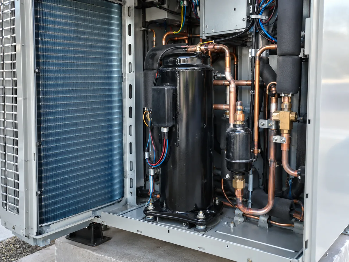
An expansion device sits between the high-pressure liquid side of the refrigeration circuit and the low-pressure evaporator side. It creates the restriction needed for a pressure drop and meters how much refrigerant enters the evaporator.
After the pressure drops, part of the liquid refrigerant can flash into vapor. The resulting low-pressure refrigerant mixture enters the evaporator and absorbs heat.
Scope of this guide: this page helps you compare expansion-device families and understand which system conditions change the direction. It does not select an exact TXV, EEV, capillary tube, or fixed-orifice size for a specific equipment model.
The harder part is controlling the amount of refrigerant entering the evaporator. If refrigerant feed is too low, part of the evaporator may be underused and the vapor leaving the coil can become excessively warm. HVAC technicians describe this using superheat, which is how far the vapor temperature is above the refrigerant’s saturation temperature at the same pressure.
When you need refrigerant-specific pressure, saturation, density, enthalpy, or other thermophysical-property data, use a traceable property source such as NIST REFPROP rather than a generic web chart.
If refrigerant feed is too high, outlet superheat can become too low. Under severe conditions, liquid refrigerant may leave the evaporator and return toward the compressor. This is one reason refrigerant metering cannot be reduced to choosing a valve by pipe connection alone.
Different expansion devices solve this control problem in different ways: a fixed geometry, evaporator pressure, outlet superheat, refrigerant liquid level, or an electronic controller using sensor inputs.
What Changes Refrigerant Flow Through the Device?
Three changes are especially important:
- The pressure difference changes. Refrigerant flow through a restriction or valve can change even when the physical opening stays the same.
- The refrigerant condition changes. A change in refrigerant, liquid condition, or operating pressure can change how the same device performs.
- The control position or command changes. A TXV can move in response to superheat, while an EEV can be repositioned by its controller. A fixed restriction cannot actively change its opening.
This is why the same device can behave differently when the operating condition changes, and why a component should not be judged from its name or connection size alone.
3. Fixed Orifice vs TXV vs EEV: Three Control Approaches to Compare First
For modern DX HVAC, three useful control approaches to compare are fixed restrictions, TXVs, and EEVs. They represent fixed metering, mechanical superheat control, and electronic refrigerant control. None is universally best.
| Decision factor | Fixed orifice / piston | TXV / TEV | EEV / EXV |
|---|---|---|---|
| Opening | Fixed | Mechanically variable | Electronically variable |
| Main control principle | Fixed restriction | Evaporator-outlet superheat | Controller responding to sensor inputs |
| Load response | Opening does not change | Valve mechanically changes opening | Controller commands valve position |
| Separate electronic valve controller | No | No | Yes |
| Typical strength | Simplicity | Automatic mechanical superheat control | Broad and flexible electronic control |
| Main dependency | Correct matched-system design and charge | Correct sizing, sensing, and pressure conditions | Correct valve, sensors, controller, wiring, and settings |
| Main mistake to avoid | Assuming one restriction fits different circuits | Selecting only by connection size or nominal capacity | Treating the valve body separately from the control system |
How Changing Conditions Affect the Three Control Approaches
| Condition | Fixed orifice / piston | TXV / TEV | EEV / EXV |
|---|---|---|---|
| System stays close to one designed operating condition | Can work well when the complete circuit is matched to the restriction | Regulates superheat as conditions move around the design point | Can regulate electronically, but the extra control system may not add useful value if the application does not need it |
| Evaporator load changes significantly | Opening remains fixed and cannot actively follow the load | Mechanically changes refrigerant feed in response to superheat | Controller can reposition the valve using sensor inputs |
| Compressor speed varies across a broad range | Fixed opening cannot actively follow compressor modulation | Can respond mechanically within the valve’s application range | Electronic control becomes more relevant because valve position can follow changing system demand |
| Sensor or controller information is wrong | The restriction itself is unaffected by sensor data | Mechanical control does not depend on a separate electronic valve controller | Control can be poor even when the valve body is mechanically sound |
| Refrigerant or operating condition changes | The original restriction may no longer match the circuit | Valve capacity and application must be rechecked | Valve operating range, controller logic, and sensor setup must be rechecked |
Start with the control problem, not the technology label:
- Start with a fixed restriction when the complete circuit is already factory-matched and the expected operating range is relatively narrow.
- Start with a TXV when the application needs mechanical superheat control as evaporator load changes.
- Start with an EEV when the application needs electronic control across a broad range and the valve, controller, sensors, and operating range can be verified together.
Do not upgrade to an EEV only because it is electronically controlled. More control capability is useful only when the system needs it.
The device did not suddenly become better or worse. The operating conditions changed, so the control requirement changed.
Why an EEV Is Not Automatically the Better Answer
A small factory-matched system operating within a narrow design range may not need the sensors, controller, wiring, and control logic required by an EEV. If the compressor, coil, refrigerant charge, and fixed restriction have already been designed and validated as one matched circuit, replacing the restriction with an electronic valve does not automatically improve the system.
The opposite can also be true. When compressor speed and evaporator load vary widely, the inability of a fixed opening to actively change becomes more important, so electronic control may become more useful.
More control capability is valuable only when the system needs it and the valve, sensors, controller, and refrigerant circuit can support it.
Fixed Orifice / Piston: A Fixed Restriction
A fixed orifice meters refrigerant through an opening that does not change size. This simplicity can work well when the compressor, evaporator, refrigerant charge, restriction, and expected operating range have been designed to work together as one matched circuit.
Refrigerant flow through the device still changes as the pressure difference and refrigerant condition change, but the restriction itself cannot actively open or close to compensate for a changing load.
A fixed orifice is therefore not automatically inferior to a controllable valve. It becomes a poor shortcut when someone assumes that a restriction from one refrigerant circuit can be transferred to another because the nominal capacity looks similar.
Before moving beyond a preliminary direction, verify the refrigerant, specified restriction, charge strategy, design conditions, and matched circuit.
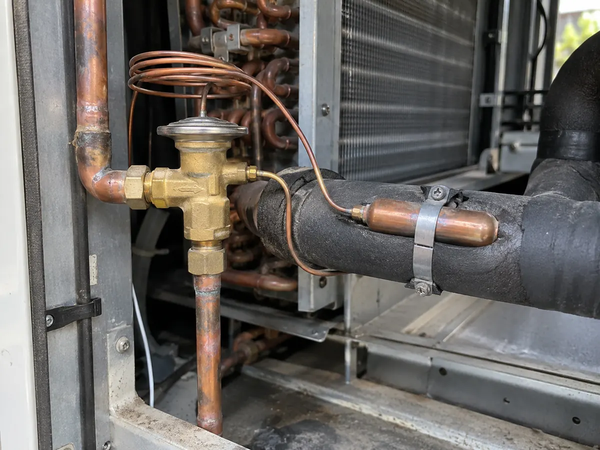
TXV / TEV: Mechanical Superheat Control
A thermostatic expansion valve, commonly called a TXV or TEV, changes refrigerant flow primarily in response to evaporator-outlet superheat. ASHRAE’s Refrigerant Control Devices chapter describes the TXV as controlling liquid refrigerant entering the evaporator in response to the superheat of gas leaving the evaporator.
This allows the TXV to adjust refrigerant feed as evaporator conditions change. It does not mean every TXV with the same pipe connection or nominal capacity is interchangeable.
Selection must consider the refrigerant, design evaporating condition, the temperature and state of liquid refrigerant entering the valve, and the pressure difference actually available across the valve after other system losses. The AHRI 750/751 performance-rating standard for thermostatic refrigerant expansion valves defines capacity using conditions that include liquid refrigerant temperature, saturated evaporator temperature, pressure difference across the valve, and superheat conditions. ASHRAE’s Refrigerant Control Devices chapter also explains that valve capacity changes with evaporator temperature, valve pressure drop, liquid condition, system pressure losses, and the choice of internal or external equalization. That is why pipe size or nameplate tonnage alone is not a complete TXV selection method.
Before moving beyond a preliminary direction, verify those conditions against the equipment and component data rather than selecting from connection size alone.
EEV / EXV: Electronic Refrigerant Control
An electronic expansion valve changes its opening through an electronic actuator, while a controller decides how the valve should move using system information such as pressure and temperature sensor inputs. ASHRAE states that applying an electric expansion valve requires a valve, controller, and control sensors.
That control architecture—the way the valve, sensors, and controller work together—can be useful when the operating range changes widely, including systems where compressor speed also changes. As an inverter compressor moves through its operating range, refrigerant-flow requirements can change with the system condition. For more context on modulation, see HVAC compressor types.
An EEV is not simply a “better TXV.” The valve body is only one part of the control system. ASHRAE states that applying an electric expansion valve requires the valve, a controller, and control sensors, which can include pressure and temperature sensors. The AHRI 1370/1371 performance-rating standard for electronic expansion valves provides the formal framework for definitions, testing, published ratings, and rating conditions. The controller, sensors, wiring, operating range, and required flow direction still have to work together in the actual system.

Before moving beyond a preliminary direction, verify the refrigerant, required operating range, controller compatibility, sensor arrangement, control logic, and flow direction.
Do Not Use These Selection Shortcuts
| Shortcut | Why it fails |
|---|---|
| “Higher-tech valve = better system” | Control complexity only helps when the application needs it and the full control system is compatible. |
| “Same tonnage = same TXV” | TXV capacity changes with refrigerant, liquid condition, evaporating condition, and pressure available across the valve. |
| “Same pipe connection = compatible replacement” | Physical fit does not prove operating fit. |
| “Variable-speed = any EEV” | The valve, controller, sensors, operating range, and flow direction must be checked together. |
| “High superheat = bad TXV” | Low charge, upstream restrictions, load/airflow problems, sensing errors, and other faults can create similar symptoms. |
4. The Other Expansion Devices and Where They Fit
The remaining expansion-device groups are important, but they do not need the same weight in every modern comfort-HVAC decision. The useful question is not only what each device is, but how to recognize the type of control problem it is meant to solve.
Capillary Tube
A capillary tube is a long, narrow tube that creates resistance to refrigerant flow. Its inside diameter, length, pressure difference, and refrigerant condition affect its metering behavior. It has no moving control parts and cannot actively change its restriction.
Capillary tubes can be useful in small systems engineered and charged as a matched package. Their simplicity is an advantage, but it also means the complete refrigerant circuit must be designed around the tube.
How to recognize this situation: the system normally uses a factory-defined capillary tube as part of a complete matched refrigerant circuit, with no sensing bulb, electronic actuator, or automatic valve-position control.
Do not confuse this with a universally interchangeable fixed part. If the compressor, coil, refrigerant, charge strategy, or operating condition changes, do not assume the original capillary selection remains valid.
Automatic or Constant-Pressure Expansion Valve
An automatic expansion valve, also called a constant-pressure expansion valve or AEV, responds primarily to evaporator pressure. Unlike a TXV, it does not use evaporator-outlet superheat as its primary control target.
Because its response to changing evaporator load differs from TXV control, it is mainly suited to applications where evaporator loading remains relatively stable.
How to recognize this situation: the application is trying to maintain an evaporator-pressure condition rather than directly regulate evaporator-outlet superheat.
Do not confuse an AEV with a TXV. Both can change their opening automatically, but they react to different variables. If the real requirement is superheat control across changing load, the two should not be treated as interchangeable solutions.
Float-Type Expansion Valves
Float systems respond to refrigerant liquid level rather than superheat. They are associated especially with flooded refrigeration arrangements, where liquid refrigerant is intentionally maintained in the evaporator or vessel and liquid level becomes a control variable.
How to recognize this situation: the control problem is maintaining refrigerant liquid level in a flooded evaporator or vessel, not simply controlling superheat at the outlet of a normal direct-expansion coil.
Do not confuse flooded level control with normal DX superheat control. When identifying an unfamiliar system, ask whether the device is trying to maintain liquid level, evaporator pressure, outlet superheat, a fixed restriction, or an electronic control target.
Manual Expansion Valve
A manual expansion valve is adjusted by hand. Its opening remains where it was set until someone changes it. It can meter refrigerant and create the required pressure restriction, but it does not automatically respond to changing superheat, evaporator pressure, liquid level, or cooling load.
How to recognize this situation: valve position is intentionally set by an operator or commissioning procedure and does not automatically follow changing load.
Do not confuse manual adjustment with automatic regulation. If the system must respond automatically as load changes during normal operation, manual positioning alone is not the same control solution as TXV, AEV, or EEV regulation.
5. Which Expansion Device Fits Different HVAC Systems?
Different HVAC and refrigeration systems call for different metering logic. The table below identifies which type of expansion device is reasonable to investigate first, when that choice should not be treated as the default answer, and what should be verified before approving the direction. It does not select an exact valve or restriction.
First Identify These Three Conditions
Before choosing a row in the table, identify:
1. Does compressor capacity stay mostly fixed or vary across a broad range? 2. Does refrigerant flow stay in one direction, or reverse between heating and cooling? 3. What is the system actually trying to control: a fixed restriction, evaporator pressure, outlet superheat, liquid level, or an electronic target?
If these three points are still unknown, do not jump directly to a valve type. Stop at system identification until the refrigerant circuit and control requirement are clearer.
| System or condition | Check first | Do not default to this when… | Verify before approval |
|---|---|---|---|
| Small factory-matched system with a narrow design range | Capillary tube or fixed restriction may fit | Do not replace the designed restriction simply because another part has the same nominal capacity or connection | Refrigerant, specified restriction, charge strategy, compressor/coil match, and design conditions |
| Conventional direct-expansion (DX) system with changing evaporator load | TXV is a reasonable type to evaluate | Do not select a TXV from pipe size or nominal tonnage alone | Refrigerant, evaporating condition, liquid condition, available valve pressure difference, sensing/equalization, and flow direction |
| Variable-speed system with a broad load range | EEV becomes more relevant | Do not assume any EEV is suitable only because the compressor is inverter-driven | Valve operating range, controller compatibility, pressure/temperature sensors, control logic, and required flow direction |
| Stable-load system that needs evaporator-pressure control | AEV may be relevant | Do not substitute an AEV where the application requires outlet-superheat control across changing load | Load stability, target evaporator-pressure control, refrigerant, and available pressure difference |
| Flooded refrigeration system | Float-level control may be appropriate | Do not treat a flooded evaporator as a normal DX superheat-control application | Actual flooded circuit, required liquid-level control, refrigerant, and vessel/evaporator arrangement |
| Reversible heat pump | Verify the actual circuit before choosing a metering direction | Do not assume one universal device arrangement will serve both heating and cooling | Heating/cooling flow paths, check-valve bypasses or separate devices, bidirectional capability, controller logic, and exact model circuit |
Three selection rules
- Stable and factory-matched does not automatically need more control complexity.
- Wider load variation increases the importance of refrigerant-flow control, but it does not automatically select the exact device.
- Reversible flow and electronic control must be checked against the actual model circuit—not inferred from the words “heat pump” or “inverter.”
These directions identify what type of device is reasonable to investigate first. They do not select a valve model. If the refrigerant, actual operating conditions, load range, compressor speed changes with load (compressor modulation), refrigerant-flow direction, or equipment circuit is unknown, stop at the device-type direction rather than presenting an exact component as confirmed.
Combined Condition Example: Variable-Speed + Reversible Heat Pump
A variable-speed reversible heat pump can combine two challenges at the same time:
- Load changes: compressor speed changes, so the required refrigerant feed can change.
- Flow changes: switching between heating and cooling can change the refrigerant path and active metering path.
Therefore, “variable-speed = EEV” is not a complete selection rule. Verify the controller range, pressure/temperature sensors, heating/cooling flow path, and the exact model schematic. The actual design may use separate metering devices with check-valve bypasses, a bidirectional device, or another model-specific arrangement.
6. Why Pipe Size or Nominal Capacity Is Not Enough
Pipe size and nominal HVAC capacity are not enough to confirm an expansion device. A connection size only shows physical fit; it does not prove that the device can meter the correct refrigerant flow at the actual pressure, temperature, and load condition where the system must operate (the operating point).
Airproz engineering rule: Physical fit is not engineering fit. A valve can have the same connection size and still be wrong for the system because the refrigerant, evaporating condition, available pressure difference, sensing method, flow direction, or control range is different.
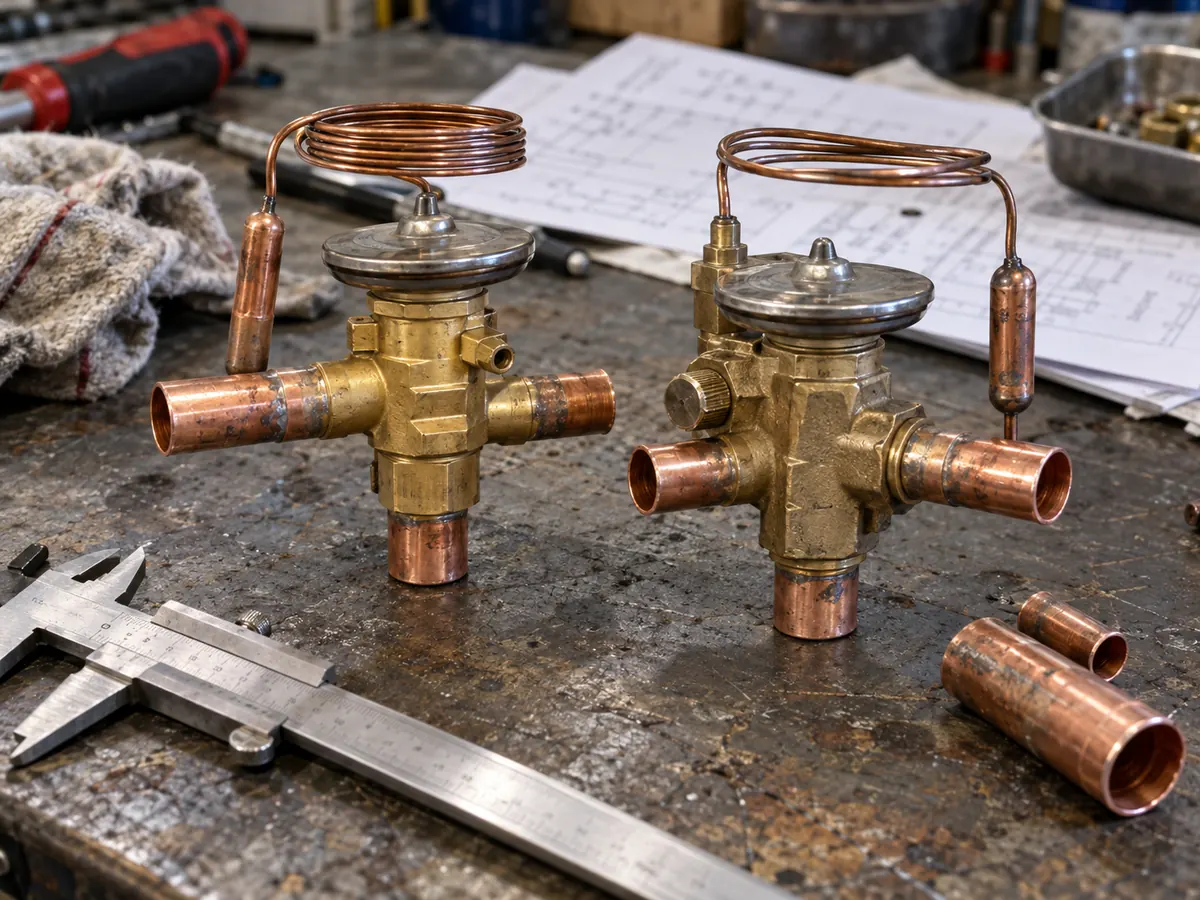
The same limitation applies to a label such as a nominal system capacity. The HVAC unit’s rated capacity does not by itself define the refrigerant flow required through a TXV or EEV at a particular evaporating condition, liquid condition, or available pressure difference.
For a TXV, the useful selection question is closer to: What refrigerant flow must the valve handle at the real evaporating condition and the pressure difference actually available across the valve after other system losses?
That net pressure difference is affected by more than compressor discharge and suction pressure. Piping, filter-driers, distributors, heat-exchanger passages, and other components can consume part of the available pressure.
The same system-level principle applies to an EEV. It also needs a compatible operating range, control architecture, sensor arrangement, and flow-direction capability.
Example: Same Nominal Capacity, Different TXV Requirement
Two systems can have similar nominal HVAC capacity and similar pipe connections but still place different demands on a TXV. If the refrigerant, evaporating condition, liquid condition entering the valve, distributor pressure loss, or other system pressure losses differ, the pressure difference actually available across the valve also changes.
The same catalog valve should therefore not automatically be assumed to provide the same useful capacity in both applications.
Physical fit is not engineering fit.
One Number Is Not Enough
| What you know | What it can tell you | What it cannot prove by itself |
|---|---|---|
| Nominal HVAC capacity | The general equipment capacity category | The exact expansion-valve capacity required at the real operating condition |
| Connection size | Whether a component may physically connect to the piping | Whether the component is suitable for the refrigerant, pressure conditions, load range, or control method |
| High superheat | The evaporator may be underfed or the measured condition needs investigation | That the TXV is definitely undersized or faulty |
Three shortcuts should therefore be avoided:
- Same pipe size does not prove compatibility.
- Same nominal capacity does not prove correct valve capacity.
- Same device family does not prove two components are interchangeable.
The practical sequence is to identify the refrigerant, real operating conditions, load range, control method, pressure conditions, and refrigerant-flow direction before confirming the component. This is a system-level decision, not a connection-size decision.
7. What Should Be Verified Before You Approve the Expansion-Device Setup?
Naming a TXV, EEV, or fixed restriction is enough for a preliminary device-type discussion, but not for final component or model approval. Once the project reaches final approval, the proposal should show enough system information to verify that the metering method matches the actual HVAC or refrigeration circuit.
| What to confirm | Why it matters | What you should receive or check |
|---|---|---|
| Exact refrigerant | Expansion-device capacity and control behavior depend on the refrigerant | Selected refrigerant shown in the model or component technical data |
| Exact HVAC or refrigeration model | The metering arrangement is tied to the real circuit, not just the product family | Model datasheet, technical manual, or refrigerant-circuit information |
| Design operating conditions | The component must work at the temperatures, pressures, and load range the project will actually see | Design temperatures, load condition, and other applicable operating data |
| Expansion-device type and control method | Confirms whether the circuit uses a fixed restriction, mechanical superheat control, pressure control, level control, or electronic control | Circuit diagram, component specification, or model technical documentation |
| TXV sensing and equalization arrangement, when applicable | Incorrect pressure sensing can change how the valve controls superheat | TXV application data showing sensing/equalization arrangement and flow direction |
| EEV controller and sensors, when applicable | An EEV cannot be approved as a valve body alone | Controller, pressure/temperature sensor, wiring, and control information for the selected system |
| Reversible-flow arrangement, when applicable | Heating and cooling can send refrigerant through different paths | Refrigerant schematic showing check valves, separate metering paths, or bidirectional control |
| Relevant technical or test documentation | Lets the project team check that the proposed system matches the stated operating requirements | Datasheet, manual, wiring diagram, and available model-specific technical/test information |
If the exact model or circuit has not been selected yet, stop at the device-type direction rather than presenting a component as confirmed. Once final component or model approval is required, the supplier should identify the model, refrigerant circuit, operating conditions, and control arrangement that support the choice. This does not mean every project needs a separate valve-calculation report; it means the final metering arrangement should be traceable to the actual system being supplied.
Stop Rules
- Stop at device-type direction if the exact equipment model has not yet been selected.
- Do not approve an EEV as a standalone valve if controller and sensor information is missing.
- Do not approve a replacement TXV using only nominal capacity or connection size.
These stop rules are intended to prevent a preliminary engineering direction from being presented as a completed component selection.
Which Reference Answers Which Question?
| Authority | Use it for | Do not use it for |
|---|---|---|
| ASHRAE Handbook — Refrigerant Control Devices | TXV, EEV and AEV control principles; superheat behavior; equalization; application boundaries; system-level refrigerant-control relationships | Exact selection of an Airproz model or a specific third-party component |
| AHRI 750/751 — Thermostatic Refrigerant Expansion Valves | TXV definitions, test requirements, rating requirements, published ratings, and the operating conditions used to establish valve capacity | Choosing a TXV from nominal tonnage or connection size alone |
| AHRI 1370/1371 — Electronic Expansion Valves | EEV definitions, test requirements, rating requirements, published ratings, and rating conditions | Proving that every inverter or variable-speed system requires the same EEV arrangement |
| NIST REFPROP | Refrigerant thermophysical properties such as pressure-temperature relationships, vapor pressure, density and enthalpy | Selecting the complete HVAC system or confirming a valve/controller combination |
8. What Can Happen If the Metering Method Is Wrong?
A poor metering match does more than create a technical inconvenience. It can affect system output, commissioning stability, compressor protection, and future service work. The exact result depends on the circuit and operating condition, but the following consequences are practical warning signs.
| Poor match or control problem | What can happen in the system | Operating / project impact |
|---|---|---|
| Persistent underfeeding | Part of the evaporator may be underused and outlet superheat can rise | Reduced heating/cooling output and poor system performance |
| Excessive refrigerant feed | Outlet superheat can become too low and the risk of liquid refrigerant reaching the suction line can increase | Unstable operation, protection trips, or compressor damage risk if liquid return becomes severe |
| Control method does not match the load range | Refrigerant flow may not follow changing system demand well | Poor performance away from the design condition and harder commissioning |
| Incorrect EEV control setup | Valve position may not match the real pressure/temperature condition | Hunting, unstable operation, repeat adjustment, or additional service work |
| Incorrect replacement device | The new component may not match the refrigerant, capacity, pressure conditions, sensing, or flow direction | Repeat diagnosis, avoidable downtime, and unnecessary parts replacement |
These outcomes are reasons to verify the complete refrigerant circuit rather than treating the expansion device as an isolated part. Their severity depends on the circuit and operating condition, so they are risk patterns rather than guaranteed outcomes. The next section explains how to separate a possible metering problem from other causes before a component is blamed.
9. Common Expansion-Valve Symptoms: What They Do Not Prove
High superheat, low superheat, hunting, or reduced capacity can point toward refrigerant-metering problems, but none of these observations proves that the expansion device itself has failed.
| Observation | Metering-related possibility | Other causes to check | Verify first |
|---|---|---|---|
| High superheat | Valve or restriction may be underfeeding | Low refrigerant charge, flash gas before the device, liquid-line restriction, or low evaporator load | Pressures and temperatures, charge procedure, upstream restriction, and actual load condition |
| Very low superheat | Refrigerant feed may be excessive for the current condition | Air/water-flow problems, load changes, sensor error, or other circuit conditions | Measured superheat, load/flow condition, sensor accuracy, and applicable control settings |
| Unstable superheat or hunting | Valve sizing, sensing, or control may be unstable | TXV bulb/equalizer issues, EEV sensor/controller issues, poor refrigerant distribution, or rapid load changes | Measured superheat over time plus sensing, equalization, sensor, or controller inputs |
| Low cooling or heating capacity | Refrigerant feed may be insufficient | Airflow, water flow, compressor performance, heat-exchanger condition, charge, or restriction elsewhere in the circuit | Complete operating condition before replacing the metering device |
Counterexample: Correct EEV Valve Body, Wrong Control Inputs
An EEV can be mechanically capable of the required refrigerant flow and still control poorly if a pressure sensor is inaccurate, a temperature sensor is positioned incorrectly, wiring is faulty, or controller parameters do not match the system.
The visible symptom may be hunting, unstable superheat, or poor refrigerant feed. The wrong shortcut is to conclude that the EEV valve body has failed.
The better verification path is to compare the valve command, sensor readings, wiring, controller settings, and measured operating condition before replacing the valve.
For a TXV system, sensing-bulb condition and location, pressure sensing, available pressure drop, equalization arrangement, and installation details can matter in the same way: the visible symptom must be connected back to the actual control mechanism.
When diagnosis is required, qualified service personnel should compare the relevant measured operating conditions—such as superheat and subcooling where applicable, pressures and temperatures, air or water flow, sensor readings, and controller commands—with the equipment procedure before blaming the metering device. Refrigerant charging should also follow the equipment procedure rather than a generic shortcut; see how refrigerant charging is handled in a heat-pump context for related system-level considerations.
The practical rule is simple: diagnose the operating condition before replacing the metering device.
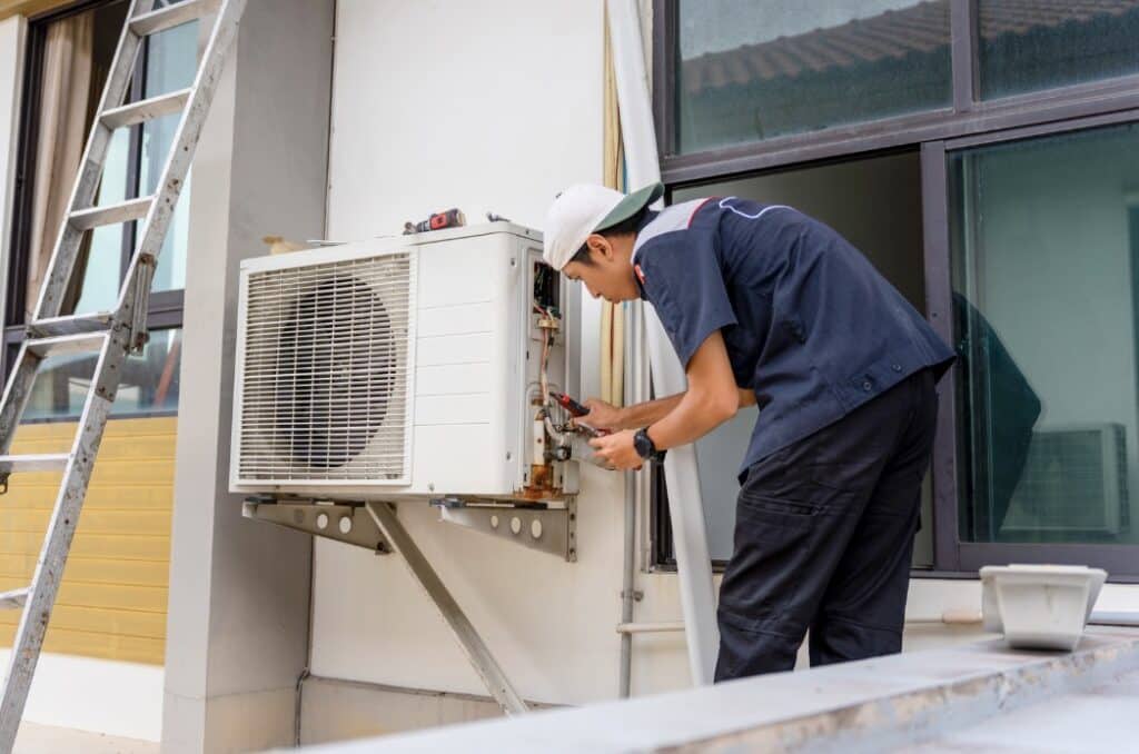
Refrigerant circuits can operate at high pressure, and some refrigerants are flammable. Opening the refrigerant circuit, recovering or charging refrigerant, brazing, or replacing a valve should be performed by qualified personnel using the procedures required for the refrigerant, equipment, and destination market.
10. Before You Approve an Airproz HVAC System
What We Check
For an Airproz HVAC selection, we check the application and the selected system before confirming the metering direction. The purpose is not to choose a valve from a connection size; it is to connect the refrigerant-control arrangement to the actual model and project conditions.
| What we check | Why it can change the metering decision |
|---|---|
| Refrigerant and selected model | The expansion-device arrangement must match the actual refrigerant circuit used by that model. |
| Compressor operating range | A compressor that stays near one speed and a compressor that speeds up and slows down with load can create different control requirements. |
| Evaporator operating conditions | The required refrigerant feed changes with the actual pressure, temperature, and load condition where the system must operate. |
| Heating and cooling flow paths | In a reversible heat pump, refrigerant can travel through different paths in heating and cooling, so the metering arrangement must match the real circuit. |
| Controller and sensor arrangement | An EEV must work with the actual controller, pressure/temperature sensors, wiring, and control logic. |
| Pressure available across the valve | TXV capacity depends on the pressure difference actually left for the valve after other system pressure losses. |
Airproz engineering rule: do not confirm an expansion-device configuration from nominal capacity or connection size alone. First identify the selected model, refrigerant circuit, real operating conditions, and control method. Exact component confirmation remains model-specific.

What You Can Ask Airproz to Verify
Before ordering, ask for information tied to the exact selected model and destination market. This is more useful than a generic “professional supplier” claim.
| Ask for | Why it matters |
|---|---|
| Exact selected model | Prevents a product-family recommendation from being mistaken for a final model configuration. |
| Applicable datasheet, manual, wiring/circuit information | Lets you trace the proposal to real model documentation. |
| Certification scope for the exact model/market where required | Prevents assuming one certificate covers every series or configuration. |
| Agreed inspection and QC scope | Clarifies what will actually be checked before shipment. |
| Model-specific refrigerant/control information | Confirms the metering arrangement against the real circuit rather than a generic product description. |
Airproz’s current public purchasing information states that factory visits can be arranged by appointment and that third-party factory audits or pre-shipment inspections can also be arranged. Model-specific document and certification availability should still be confirmed for the exact order. See the Airproz HVAC FAQ and the Airproz supplier-verification guide.
11. Frequently Asked Questions
What are the three practical expansion-device groups to compare in modern HVAC?
For many modern direct-expansion HVAC systems, three useful control approaches to compare first are fixed restrictions, TXVs, and EEVs. They represent fixed metering, mechanical superheat control, and electronic refrigerant control. This is a practical comparison framework, not a market-share ranking.
Is a fixed orifice really an expansion valve?
It performs the pressure-reduction and refrigerant-metering job of an expansion device, but it does not have an adjustable valve opening. That is why expansion device or metering device is often the more accurate broad term.
When should I consider an EEV instead of a TXV or fixed orifice?
An EEV becomes more relevant when the system has a broad load range, variable-speed compressor operation, or a control strategy that needs refrigerant flow to respond to sensor data across changing conditions. That does not make an EEV automatically better than a TXV or fixed restriction. The final direction still depends on the refrigerant circuit, operating range, controller, sensors, pressure conditions, and model-specific design.
Does a heat pump use the same expansion device in heating and cooling?
Not necessarily. A reversible heat pump changes the refrigerant path between heating and cooling. Depending on the design, it may use separate metering devices, check-valve bypasses, a bidirectional electronic valve, or another model-specific arrangement. Check the actual refrigerant circuit before assuming one configuration.
Can I replace a TXV with another TXV of the same nominal size?
Not safely from nominal size alone. The replacement still needs to match the refrigerant, required capacity at the actual operating conditions, available pressure drop, pressure-sensing arrangement, connection, pressure rating, and flow direction. Exact replacement selection is outside the scope of this article and should be confirmed from the equipment and component data.
Need to Check an HVAC Configuration for Your Project?
Send Airproz the application, required capacity or load range, destination market, power supply, heating/cooling requirement, any known refrigerant or system constraints, and the existing equipment/model if this is a replacement project.
Send Your Application Conditions →
The exact TXV, EEV, fixed-restriction, or other metering arrangement remains model-specific and should be confirmed from the selected unit’s technical data and refrigerant circuit.