Start hotel heat pump water heater sizing with the busiest hot-water period. Use room count to estimate demand, then confirm the timing from metered or planned fixture use. Build an hourly demand profile for showers, kitchens, laundry, and other outlets. Then size the heat pump’s usable heating output and the tank’s usable stored energy together. Check that the system can recover before the next peak, even at the site’s design ambient temperature.
A hotel hot water system must also keep water at suitable temperatures throughout the distribution and recirculation system. That means the final design has four connected parts: demand, heating capacity, storage, and water-temperature control. This guide gives you the calculation method, a complete example, and a practical equipment brief for comparing commercial heat pump water heater proposals.
Quick sizing example: For a modeled 120-room hotel using 5,000 L of 40°C mixed water in two hours, 40 kW of actual thermal output and about 1,800 L of nominal storage pass only the simple two-hour energy calculation. A concentrated 30-minute draw could still empty that tank. The worked example below shows the shorter-interval test, loop losses and how to compare larger storage or different heat-pump capacity.
What Do You Need to Size a Hotel Heat Pump Water Heater?
You need an hourly hot-water load, incoming and delivery temperatures, design-day heat pump output, useful tank storage, and the hours available for recovery. Pair room count with a timed draw profile to identify overlapping showers, kitchen work, laundry and other shared hot-water duties.
Start by gathering the following inputs. If the hotel is already operating, metered draw and plant records are stronger than a generic hotel-per-room figure.
| Project input | What to collect | How it changes the design |
|---|---|---|
| Guest demand | Rooms, expected guests, occupancy on busy days, shower and bath flow rates and use time | Sets the main shower draw and its timing |
| Shared services | On-site laundry, restaurant, dishwashing, spa, fitness showers and staff facilities | Adds loads that may overlap with guest use |
| Timing | Draw by 15–30 minutes through the busiest periods, plus the next peak | Determines tank discharge and recovery window |
| Water temperatures | Cold inlet, required distribution temperature and storage setpoint | Converts liters into thermal kWh |
| Weather | Lowest design air temperature and high-ambient operating condition | Changes actual heat pump output and defrost behavior |
| Distribution | Circulation pipe length, insulation, measured or calculated heat loss | Adds a continuous maintenance load |
| Operation | Space, ventilation, electrical supply, backup policy and maintenance access | Limits the workable equipment arrangement |
Ask housekeeping and food-service staff whether their equipment draws hot water from the central plant. Some commercial washers and dishwashers have separate boosting heaters, while others place substantial loads on the domestic hot water system. Count each load once, at the correct water temperature.
How Do You Calculate Hotel Hot Water Demand?
Calculate water used at each delivery temperature, record when it is used, and add its heating energy for each 15–30-minute interval. Start with the busiest credible day rather than assuming every room uses the same amount at the same time.
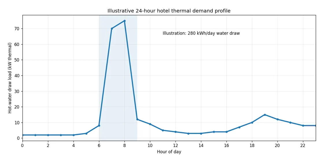
Build a demand profile instead of guessing a liters-per-room rule
For a shower group, estimate mixed-water demand as:
Mixed water (L) = number of showers × flow rate (L/min) × minutes per shower.
For example, 60 showers at 7 L/min lasting 8 minutes require 3,360 L of mixed water. If those showers are spread across two hours, the draw shape matters: 1,680 L in each hour is easier to supply than most of the volume arriving during one 30-minute period. Add kitchen, laundry and other loads in the hours when they actually operate.
| Time window | Guest showers | Kitchen / laundry | What to check |
|---|---|---|---|
| Early morning | May rise quickly | Breakfast preparation may overlap | Maximum combined draw within the hour |
| Midday | Often lower | Housekeeping and on-site laundry may rise | Whether the tank recharges before evening |
| Evening | May rise again | Restaurant and spa use may overlap | Second peak after a short recovery window |
| Overnight | Often low | Recirculation heat loss continues | Time and capacity available to recharge storage |
For an existing hotel, log hot-water flow and temperatures over representative high-occupancy days. For a new hotel, use the actual fixture schedule and the expected guest behavior, then test alternative occupancy and use patterns. The ASHRAE Handbook’s service-water-heating chapter describes why hotel categories differ and why old average-use tables alone are not enough for final sizing.
Use a 15- or 30-minute load worksheet for the busiest two periods. Meter flow where possible; otherwise list the number of uses, flow rate and duration for each activity. Record the source of every assumption so the hotel team can correct it when readings become available.
| Time interval | Guest showers (L and °C) | Kitchen / laundry / spa (L and °C) | Source of input | Thermal demand (kWh) |
|---|---|---|---|---|
| 06:00–06:30 | Metered draw or fixtures × flow × minutes | Separate volumes and use temperatures | Meter / equipment duty / estimate | Convert each use separately |
| 06:30–07:00 | Record again | Record again | Same basis | Add heat from all loads |
| 07:00–07:30 | Record again | Record again | Same basis | Add heat from all loads |
| 07:30–08:00 | Record again | Record again | Same basis | Add heat from all loads |
| Next busy period | Repeat the intervals | Repeat the intervals | Busy-day profile | Test recovery first |
Convert each hot-water duty to thermal kWh at its own delivery temperature before adding the loads. A 60°C kitchen duty and a 40°C shower draw use different temperature rises above cold inlet water. Count the preheated water an appliance takes from the central plant; assign its separately heated portion to that appliance. For an operating hotel, enter metered 15–30-minute readings. For a new hotel, enter fixture flow rates and expected use times, then test the busiest overlap.
Convert delivered mixed water into heating energy
The useful thermal energy to heat water is:
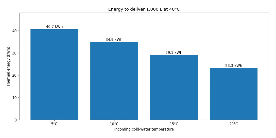
Energy (kWh) = volume (L) × 4.186 × (delivery temperature − cold inlet temperature) ÷ 3,600.
This assumes water density close to 1 kg/L, with temperatures in °C. A 1,000 L draw at 40°C when the cold supply is 15°C takes about 29.1 kWh of heat. For the same volume at a 5°C inlet, it takes about 40.7 kWh. That is why two hotels with identical occupancy can need different water-heating capacities.
Where water is stored hotter than it is delivered, calculate the hot-water share using:
Hot fraction of mixed draw = (delivery temperature − cold inlet temperature) ÷ (storage temperature − cold inlet temperature).
At 40°C delivery, 15°C inlet and 60°C storage, the fraction is 25/45 = 0.556. Thus 1,000 L of 40°C water represents approximately 556 L at 60°C mixed with 444 L of incoming cold water in an ideal heat-balance calculation. The usable stored kWh depends on stratification, controls, piping and the lowest acceptable delivery temperature. Use that available energy when sizing the tank.
How Do You Match Heat Pump Capacity and Storage Tank Size?
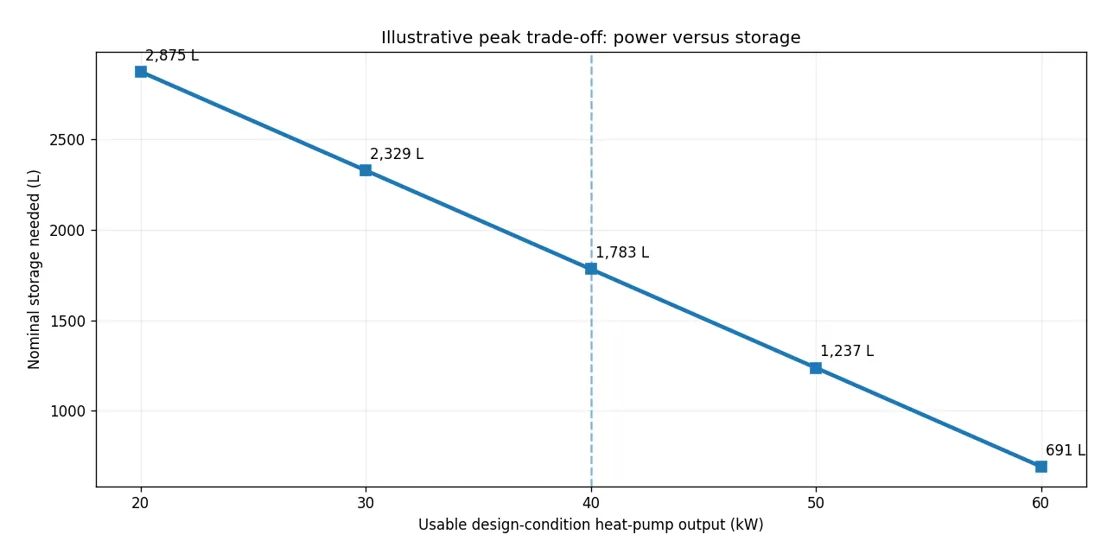
The heat pump supplies heat continuously; the tank covers the difference when guest demand is faster than the heat pump can produce it. Choose a pair of values that meets the peak and allows the tank to recharge before the next one. A larger tank can allow less heat pump power, but the answer depends on the full daily load curve.
Calculate the peak-period energy shortfall
For a first estimate with nearly constant heating output during a peak:
Peak shortfall (kWh) = peak hot-water energy (kWh) − heat pump output at design conditions (kW) × peak duration (h).
Use zero if the result is negative. The required useful stored energy must cover that shortfall, along with losses and any other coincident loads not included in the draw. For accurate sizing, calculate the running storage balance through short time steps instead of looking at just one hour: a short, sharp shower surge can empty a tank even when the whole-hour average appears acceptable.
Convert the energy shortfall into a physical tank size
Nominal tank liters = required useful storage energy (kWh) × 3,600 ÷ [4.186 × (storage °C − cold inlet °C) × usable fraction].
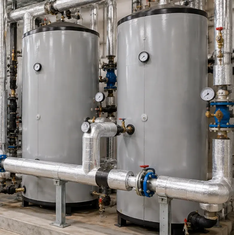
A usable fraction represents the share of installed storage that can actually be delivered at the required temperature before the tank is considered discharged. Use a 70% usable-storage fraction for this worked example. For a real tank, use the usable-energy figure supported by its stratification, sensor positions, controls and minimum delivery temperature. The ASHRAE chapter discusses net usable storage and the effect of tank utilization.
Size the tank from the busiest 15–30-minute draw, the heat pump’s verified net output and the time available to recharge before the next peak. Recalculate the stored-energy balance through each busy interval. The DOE Building America central hot-water guide likewise treats heating output and storage as a paired sizing decision.
Compare heat pump output with storage volume
More installed tank volume can cover a short peak while a smaller heat pump catches up, but daily energy and available recovery hours still set a lower limit on heat-pump output. The following first-pass comparison uses the exact same two-hour load as the 120-room illustration below. The values exclude loop losses during the peak and use a hypothetical 70% usable storage factor.
| Design-condition heat output | Two-hour useful tank deficit | Nominal storage estimate | Ideal equivalent full-output hours for 328 kWh/day |
|---|---|---|---|
| 30 kW | 85.3 kWh | about 2,330 L | 10.9 h/day |
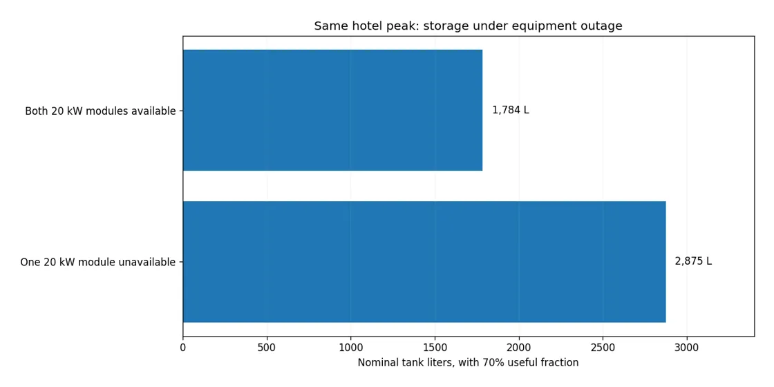
| 40 kW | 65.3 kWh | about 1,784 L | 8.2 h/day |
| 50 kW | 45.3 kWh | about 1,238 L | 6.6 h/day |
Compare these three initial combinations against the same hotel service target. Check the busiest 15–30-minute draws, loop heat loss, next-peak recovery, unit minimum output and one-unit-out duty. Keep a combination when its stored-energy balance and recovery meet the target; otherwise change the heat pump power or usable storage and recalculate. The worked example uses 328 kWh/day for the hours column, including a stated 48 kWh/day loss component.
To compare a commercial hot-water model family in this output range, see the Airproz 32/38 kW commercial hot-water heat pumps. Use the listed ratings to shortlist models, then check net heat output at the hotel’s design air and water temperatures when determining the unit count and storage volume.
Worked Example: A 120-Room Hotel With a Two-Hour Morning Peak
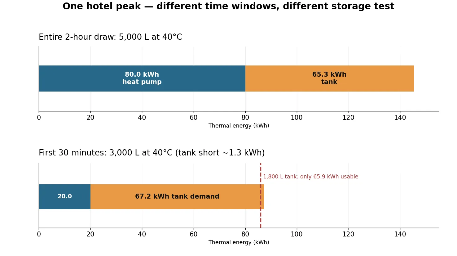
Assume a 120-room hotel draws 5,000 L of 40°C mixed water over two hours, including 3,000 L in the first 30 minutes. With 40 kW of available heating output, about 1,800 L of nominal storage covers the total two-hour energy but runs short during that first half hour. Calculate the time-step balance, loop losses and recovery window to choose the next storage-and-power combination.
| Worked-example input | Assumed value |
|---|---|
| Hotel size | 120 rooms (context only) |
| Mixed hot-water demand during morning peak | 5,000 L over 2 hours at 40°C; assumed 3,000 L in first 30 min |
| Cold incoming water | 15°C |
| Tank storage temperature for calculation | 60°C |
| Heat pump thermal output at the site’s design condition | 40 kW total |
| Usable share of installed storage | 70% (assumed; actual tank/controls must be checked) |
| Optional loop-loss test | 2 kW if carried by the primary plant; not included in Steps 1–3 |
Step 1: Find the peak heat demand
5,000 × 4.186 × (40 − 15) ÷ 3,600 = 145.3 kWh over two hours, equivalent to an average draw load of 72.7 kW. The 72.7 kW is the average thermal draw rate during these two hours; use design-condition heating output separately when sizing the heat pump.
Step 2: Subtract heat produced during the peak
40 kW × 2 hours = 80.0 kWh. The remaining energy is 145.3 − 80.0 = 65.3 kWh. At least this amount must be delivered from usable storage in the simplified example.
Step 3: Convert the shortfall to tank liters
At 60°C storage and 15°C cold inlet, each liter of useful stored hot water represents about 0.0523 kWh. The required useful volume is 65.3 ÷ 0.0523 = about 1,250 L. With a 70% assumed usable fraction, physical storage = 1,250 ÷ 0.70 = about 1,785 L. Use approximately 1,800 L of nominal storage as the first candidate from the two-hour total. Next, track usable tank energy after each 30-minute draw.
Step 4: Check the busiest 30 minutes
A two-hour average can hide a shortage in the first half hour. Assume 3,000 L of the 5,000 L arrives in the first 30 minutes, with the remaining 2,000 L spread over the next 90 minutes.
- First 30-minute heat draw: 3,000 × 4.186 × (40 − 15) ÷ 3,600 = 87.2 kWh.
- Heat pump production in that half hour: 40 × 0.5 = 20.0 kWh.
- Energy the tank must provide immediately: 67.2 kWh.
- A fully charged 1,800 L tank under the 70% example factor provides 1,800 × 0.70 × 4.186 × 45 ÷ 3,600 = 65.9 kWh.
Result: the assumed 1,800 L tank is short by about 1.3 kWh before any additional loop heat loss. It fails this 30-minute case despite passing the simplified two-hour calculation. The direct short-period energy requirement alone is equivalent to about 1,835 L nominal storage at these same idealized temperatures and usable fraction. Increase usable storage or verified heat output, then rerun the full draw-and-recharge sequence, including any loop heat supplied by the primary plant.
To check the whole peak, work forward through each time step: remaining usable tank kWh = previous usable tank kWh + net heat added during the interval − thermal hot-water draw during the interval. Limit added heat when storage is already full; use the heat pump’s actual average output, not an optimistic peak rating. If the tank falls below its permitted minimum at any point, the candidate fails.
| Modeled interval | Mixed-water draw | Thermal draw | Heat pump adds | Net tank change, excluding loop loss |
|---|---|---|---|---|
| First 30 minutes | 3,000 L | 87.2 kWh | 20.0 kWh | −67.2 kWh |
| Next 30 minutes | 650 L | 18.9 kWh | 20.0 kWh | +1.1 kWh |
| Next 30 minutes | 650 L | 18.9 kWh | 20.0 kWh | +1.1 kWh |
| Last 30 minutes | 700 L | 20.3 kWh | 20.0 kWh | −0.3 kWh |
If the hotel also has a modeled continuous 2 kW loop loss served by the primary plant, subtract another 1 kWh from storage balance for every half hour. Starting with a fully charged tank and assuming the heat pump can hold 40 kW, the two-hour deficit then rises from 65.3 to 69.3 kWh. Its minimum energy-only nominal storage estimate rises from about 1,784 L to about 1,893 L, before margin, tank discharge limits and operating controls. That figure also passes the first 30-minute calculation only under the same full-tank and continuous-output assumptions. A separate temperature-maintenance heater needs its own load, capacity and electricity accounting instead.
Step 5: Check full-day heat and the next recharge window
Assume this hotel uses 280 kWh/day for delivered water plus 48 kWh/day for distribution and tank loss, a total of 328 kWh/day. If the 48 kWh is already the full day of the same modeled 2 kW loop loss, do not add another 48 kWh. If that 48 kWh includes multiple components instead, break them down before adding any new source of loss.
At 40 kW, 328 kWh/day equals 8.2 theoretical full-output hours. To calculate recharge, start with the remaining tank energy at 08:00 after the morning peak. If the next peak starts at 18:00, update the tank balance through that 10-hour window using net heat added, ongoing guest draws and loop losses. The tank needs the required stored-energy level by 18:00. If it falls short, increase verified heating output, move controllable loads, add usable storage or size the agreed backup supply.
Step 6: Test an equipment-out day
If a hypothetical 40 kW plant comprises two 20 kW modules, and one is out, the plant contributes only 20 × 2 = 40 kWh over the two-hour draw. The water-draw deficit rises to 105.3 kWh, or about 2,875 L nominal storage using the same energy-only assumptions before additional coincident losses. A plant with three verified 20 kW modules might retain 40 kW after one stops, but N+1 is achieved only if the storage, controls, electrical supply and agreed hotel service level also pass. Check the next peak again with the impaired output.
The 60°C storage temperature is the worked example’s calculation input. Set the hotel’s operating storage temperature from its water-management plan and applicable requirements. If the plan calls for storage above 60°C, add the required booster or select equipment that can reach it. Recalculate stored energy and the equipment duty at the selected temperature.
What Changes the Correct Heat Pump Capacity on Site?
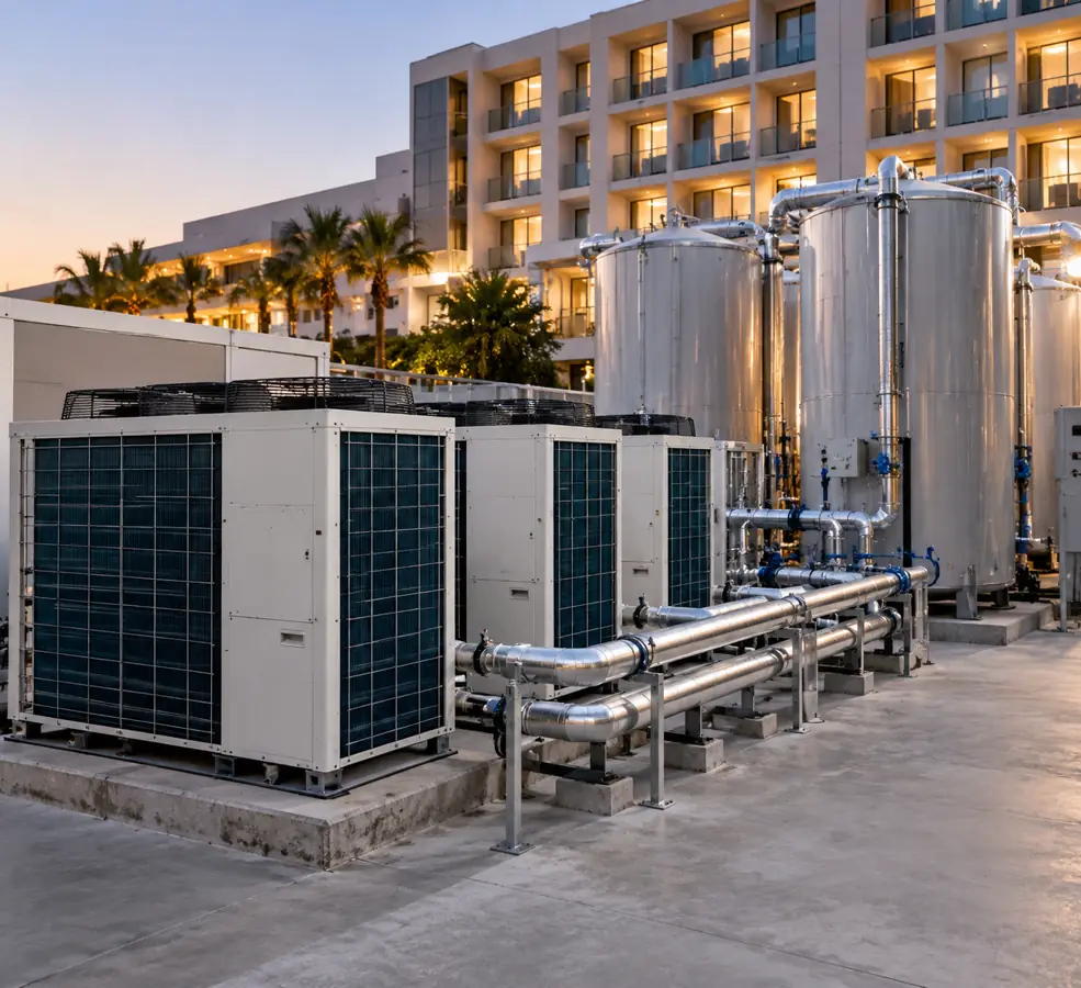
Use the unit’s documented net heating output at the required water temperature and the hotel’s design air temperature to size the system. The same commercial heat pump water heater can supply less heat when outside air becomes colder or when a higher water temperature is requested.
Weather, defrost and water temperature
Ask the supplier for the model’s net thermal heating output, electrical input and efficiency at the design air temperature, leaving-water temperature and water flow. Use the matching performance table, including defrost assumptions and stated corrections, to set the unit count and recalculate tank discharge and recovery.
Our guide to how an air-to-water heat pump works explains how outdoor air temperature, required water temperature and defrost affect heat-pump operation. Use the chosen commercial hot-water model’s performance table at the hotel’s design point for the sizing calculation.
| Confirm for every shortlisted unit | Value to compare | What changes if it differs |
|---|---|---|
| Outdoor design air temperature | °C at the hotel | Colder air or defrost may reduce usable heat output |
| Water inlet/outlet at rating | °C / °C | A hotter outlet may reduce capacity and efficiency |
| Net heating output and rating point | kW thermal + named test conditions | Use this value in the peak and recovery equations |
| Input electricity and COP | kW electrical and the same test point | Check operating cost, wiring and the seasonal model |
| Defrost and minimum modulation | Average kW and lowest stable output | Test winter recovery and short cycling |
| Water flow, pressure drop and control mode | L/min, kPa, supported staging | Verify hydraulic compatibility and backup logic |
| Evidence | Model-specific performance table and version | Resolve mismatched rating conditions before quotation acceptance |
For warm-weather hotels, also check operation at high ambient temperatures, ventilation and electrical limits. If the supplier’s performance table omits the project design point, request the matching data or select equipment with documented performance at that point.
The recirculation loop is a separate heating load
Hotels circulate hot water so distant guest rooms receive it promptly. Pipework loses heat even when no shower runs. Estimate that loss from measured or calculated pipe temperature loss, insulation, run length and hours of circulation. A continuous 2 kW loss means 48 kWh/day, whether produced by the main heat pump or an assigned temperature-maintenance heater.
Assign every heat loss to its actual heat source and count it once. If the primary plant supplies this 2 kW during a two-hour peak, add 4 kWh to that peak’s energy balance. That raises the simple energy-only nominal tank figure from around 1,784 L to around 1,893 L under the worked-example assumptions. If an independent loop heater supplies those 4 kWh, size and meter that heater separately while keeping the main storage calculation on its own assigned duty. The daily 328 kWh illustration already includes its stated 48 kWh loss; adding it again would double-count heat. The DOE Building America guidance on central hot-water systems explains why temperature maintenance needs separate attention.
| Recirculation arrangement | When it can help | What the hotel must check |
|---|---|---|
| Separate booster or swing tank | The primary heat pump mainly makes fresh hot water; loop temperature needs its own heat | Heater duty and temperature limits, electric use, controls, stratification and water-hygiene plan |
| Parallel temperature-maintenance tank / dedicated loop heat pump | Loop return can be heated apart from primary storage | Loop-heater output at return temperatures, sensors, flow, maintenance and controls |
| Shared primary heating plant | Simple layouts where the primary plant can carry both jobs | Frequent reheating, tank mixing, usable storage during shower peaks and total design-condition kW |
Select the temperature-maintenance arrangement using measured or calculated loop loss, required return temperature, equipment controls and the hotel’s water-management plan. Confirm the selected arrangement before completing piping and control drawings.
When reviewing the water-side layout, use our guide to heat-pump piping and system drawings to follow the pumps, tanks, valves and control paths. Finalize the hotel connections using the selected commercial hot-water equipment drawings and its water-management plan.
Plant room, electricity and noise
Check these constraints before counting any candidate as installable:
| Site constraint | Inspect | If the candidate fails |
|---|---|---|
| Air path and defrost drainage | Required airflow, placement and condensation route | Move equipment or revise plant-room ventilation and drainage |
| Service access and tank loading | Clearances, transport route and floor/slab load | Change arrangement or validate a structural/handling plan |
| Electrical service and controls | Voltage, phases, maximum input, protection and BMS interface | Confirm upgrade cost or select compatible equipment |
| Noise, vibration and corrosion | Guest-room exposure, mounting and local environment | Reposition, isolate or specify approved protection |
| Existing-hotel changeover | Isolation plan and occupied-hours hot-water continuity | Keep an approved temporary or retained hot-water source during commissioning |
Compare dimensioned equipment drawings with the plant-room plan. Check delivery access, maintenance clearances, floor loading, drainage, airflow and electrical connections before fixing the layout.
Should a Hotel Use One Heat Pump or a Cascade System?
Use one unit when a single machine can meet the real load, downtime plan and service constraints. Choose a staged multi-unit cascade when the hotel needs maintainability, flexible output, or a defined equipment-out service level. Room count alone is not a reliable cut-off for either option.
| Decision | Single heat pump | Multiple heat pumps / cascade |
|---|---|---|
| Heating output | One unit’s verified design-condition kW | Sum of simultaneously available, verified kW |
| Service outage | No heat-pump output if the unit fails | Remaining units provide partial or full output, depending on design |
| Part-load control | Depends on its modulation range | Units can be staged with the right controls |
| Piping and controls | Usually simpler | Requires balanced flows, staging and fault handling |
| Maintenance | One main machine to isolate | Can service one module while others operate |
| Cost and space | Fewer machines and connections | More equipment, controls and clearances |
Define the required operating capacity N, then test whether one additional module provides the agreed backup duty. If two 20 kW modules must operate to meet the design requirement, adding a third 20 kW module can create one spare module—but only if the complete tank, electrical and control system also passes the loss-of-one test. Three installed units do not prove N+1 if all three are needed to meet normal demand.
Run the one-unit-out case on the same time-based load profile as the normal case.
| Backup check | Evidence or method | Pass condition |
|---|---|---|
| Largest module offline | Remaining documented net kW at design weather | Deliver the defined reduced or full service duty |
| Storage at outage start | Remaining usable kWh, not just tank label liters | No 15–30-minute interval falls below the service minimum |
| Auxiliary heater, if adopted | Verified thermal kW, controls and available power | Covers the explicitly assigned missing duty |
| Next-peak recovery | Time until the following busy demand | Required storage is ready before the next peak |
| Normal light-load days | Lowest stable output, cycling and control sequence | Units stage without avoidable rapid on/off cycling |
A hotel can deliberately choose partial service during maintenance, but the agreed service target must be written into the specification. This makes a staged cascade a real reliability plan rather than a count of installed machines.
For hotels that need larger plant modules, compare the larger Airproz commercial hot-water heat pump models. Select unit count and backup capacity from documented design-condition output, then run the same one-unit-out storage and recovery checks for the proposed system.
What Water Temperature and Hygiene Controls Does a Hotel Need?
Set the hotel’s water-hygiene and scald-control strategy alongside heating output and storage. Guest rooms, low-use floors, long circulation branches and spas need a building water-management approach alongside the energy calculation.
The CDC guidance for Legionella control recommends storing hot water above 60°C (140°F) and keeping circulating hot water at or above about 49°C (120°F) while managing scald risk and local requirements. The delivery temperature at a shower can be lower through an approved mixing arrangement. Check the actual jurisdiction and use a water-management specialist to define storage, recirculation, monitoring and thermal-disinfection needs.
Where the required storage temperature exceeds the selected heat pump’s verified output temperature, size a booster, treatment stage or alternative approved heating arrangement. Match the control sequence to the equipment’s rated outlet range. Include low-occupancy floors, holiday operating patterns and stagnation response in the hotel’s water-management plan.
Which Airproz Product Direction Fits This Project?
Start with the hotel’s verified heating-output requirement, then compare the appropriate Airproz commercial hot-water product family at the required site conditions. Use the catalog capacity table to create a shortlist, then match each model’s documented output to the hotel’s calculated heat duty.
Airproz lists AT-series commercial hot-water heat pumps. The published model table shows AT-019K: 18 kW, AT-022K: 22 kW, AT-032K: 32 kW, and AT-038K: 38 kW as rated heating-capacity values, with 380–415V / 3-phase / 50Hz listed for the series. For a higher-demand property, the commercial heat pump category shows larger hot-water product directions. Set the unit count using each model’s documented net output at the hotel’s design air and water temperatures. Then check short-time draw, storage recharge and one-unit-out operation for the full plant.
| From the hotel design brief | What to request for the exact Airproz model | Selection result |
|---|---|---|
| Thermal kW at design air and outlet temperatures | Performance table at the matching test condition | Count only verified usable kW, not label kW |
| Minimum and peak heat duty | Modulation/staging limits and defrost duty | Test normal and low-occupancy operation |
| Water storage and loop temperature | Compatible tank/control schematic and any booster duty | Check hygiene, recirculation and recovery together |
| Electrical and physical constraints | Maximum electrical input, phase, dimensions, flow and pressure loss | Accept only configurations that fit the site |
| Project destination | Model-specific applicable approvals and supporting documents | Confirm local technical/market requirements before an order |
For a small property with separated hot-water areas, a split or integrated heat pump water heater may be worth checking. For a multi-floor hotel with one central loop, examine central storage, dedicated temperature maintenance and a properly staged commercial plant. For the exact model and project destination, request the proposed configuration, applicable approvals and matching technical documents.
How Do You Compare Operating Cost With a Boiler or Electric Heater?
Compare annual heat demand, seasonal system efficiency, local tariffs and installation costs on the same basis. Heat pumps usually use less electricity than direct electric resistance for the same delivered thermal energy, but a one-point catalog COP is not an annual system COP.
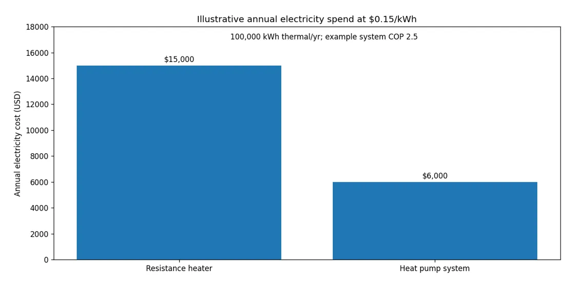
For an illustrative 100,000 kWh of annual delivered thermal heat, resistance heating at an assumed total electricity-to-delivered-heat ratio of 1.0 would use about 100,000 kWh electricity. A heat pump system with a hypothetical seasonal delivered-heat-to-all-electricity ratio of 2.5 would use 40,000 kWh. At $0.15/kWh, that is $15,000 versus $6,000, a $9,000 arithmetic difference before any demand charges, fixed tariffs or installation costs.
Use the same equipment and energy boundary for every cost comparison. When the 2.5 system ratio already includes defrost, circulation pumps, tank losses, auxiliary heat and controls, count those loads within that total. If the supplier quotes only a compressor COP at one test point, estimate pumps, boosters, standby losses and controls separately to create a comparable annual total. Keep all options at the same delivered hot-water quantity, temperature and outage-service target.
For a fuel boiler, convert fuel into delivered heat using its seasonal efficiency and the price of the fuel in consistent units. Add electricity upgrades, plumbing, tanks, noise treatment, maintenance, service access, incentives actually available to the project, and the cost of retaining backup during a retrofit. Then compare the same service level, especially during full occupancy and equipment outages.
What Should a Hotel Send to a Supplier for a Usable Sizing Quote?
Send the room count with the timed demand profile, water temperatures, design weather, recovery window and backup duty. A sound request lets competing suppliers price the same duty and shows whether their storage and heat pump capacity really work together.
- Property and loads: address/country, number of rooms, guest profile, restaurant/laundry/spa loads, expected busy-day occupancy and possible expansion.
- Draw schedule: 24-hour hot-water volume by hour, with peak 15–30-minute periods if known; include meter readings or fixture assumptions.
- Temperatures: cold-water design temperature, delivery and storage temperatures, local hygiene and scald controls, and expected loop temperature.
- Technical duty: required design-day heating output, storage assumptions, recovery window, backup performance and required redundancy.
- Site and integration: available equipment and tank footprints, air paths, weather, electrical capacity, noise limits, plant photos, pipework and controls/BMS requirements.
- Proposal evidence: capacity/COP tables at required conditions, system schematic, tanks and control strategy, certification applicable to the specific model, commissioning plan, warranty and service arrangements.
Compare three supplier proposals on the same hotel duty
Ask every supplier to answer the same questions, rather than comparing installed equipment price alone. Mark missing figures Unknown until each supplier provides documented values. Compare offers using the same project requirements.
| Same hotel requirement | Supplier A | Supplier B | Supplier C |
|---|---|---|---|
| Net thermal kW at design air/water temperatures | Provide rating evidence | Provide rating evidence | Provide rating evidence |
| Nominal tank L / validated usable kWh | Provide both | Provide both | Provide both |
| Worst 15–30-minute storage balance | Provide minimum remaining kWh | Provide minimum remaining kWh | Provide minimum remaining kWh |
| Storage ready before next peak? | Show time-step result | Show time-step result | Show time-step result |
| Loop-heating equipment and assigned losses | Identify scope | Identify scope | Identify scope |
| Largest unit out: service and backup | Show remaining duty | Show remaining duty | Show remaining duty |
| Seasonal system electricity and tariff | State included loads | State included loads | State included loads |
| Installed equipment, commissioning, warranty and service | List included / excluded | List included / excluded | List included / excluded |
Select the proposal that meets the hotel’s defined duty and service level with the strongest comparable evidence, then compare full installed and operating costs. For each offer, put storage, recirculation control, backup and commissioning into the cost comparison so the quoted packages meet the same service target.
If you are comparing commercial hot-water heat pumps for a hotel, send us your project details at Airproz. We can review the load assumptions against relevant product families and discuss which documented configuration should move to detailed system design.
Frequently Asked Questions About Hotel Heat Pump Water Heater Sizing
Can a hotel hot-water tank pass a two-hour sizing check but fail in 30 minutes?
Yes. The two-hour total can hide a heavy shower rush early in the period. In this guide’s 120-room example, 1,800 L passes a simplified two-hour heat balance but falls short by about 1.3 kWh if 3,000 L is drawn in the first 30 minutes. Check each short interval with the verified heat-pump output, usable tank energy and any coincident loop loss before selecting a tank.
Can I size a hotel heat pump water heater from room count alone?
No. Room count is a starting input. Two 120-room hotels can have very different morning shower profiles, restaurants, laundry arrangements and cold-water temperatures. Use fixture or metered consumption and a peak-hour schedule to calculate the actual duty.
Does a bigger storage tank always mean a smaller heat pump?
Not always. More useful storage can bridge a short peak, but the heat pump still needs enough time and output to recharge it before the next peak and to meet the full daily heat demand. Check the complete time-series balance, not a tank-size ratio alone.
What if the hotel’s peak demand is much higher on weekends?
Size against the selected busy-day service requirement and test its hourly shape. Weekend, conference or holiday occupancy may shift both the size and timing of showers, kitchen work and laundry. Collect peak-event data or create a documented peak-event scenario, then repeat the storage and recovery check.
Should the hotel include the recirculation loop in the sizing calculation?
Yes. The loop loses heat during hours with little or no guest draw. Estimate its heat loss separately and choose a temperature-maintenance solution that prevents loop returns from undermining the main hot-water storage operation.
Is a three-unit cascade automatically N+1?
No. N+1 means the required normal-duty capacity remains available after the planned loss of one unit. Three units only qualify if the remaining two, storage, backup and controls satisfy the specified service condition.
Can a heat pump with a 60°C outlet rating meet hotel hygiene requirements?
Only if the whole water-management design meets the required temperature and control strategy. Where the approved plan calls for storage above 60°C, a machine limited to 60°C may need a booster or a different system approach. Review CDC advice and applicable local rules together with scald protection.
Conclusion: Size the Hot Water System as One Working Plant
The right hotel heat pump water heater sizing method combines 15–30-minute hot-water demand, verified design-condition kW, usable stored kWh and enough time to recover before the next peak. Convert showers, kitchen and laundry to comparable heat loads; run the short-interval balance; then check loop heating, hygiene controls, weather, electrical limits and one-unit-out service. Use the same inputs to compare supplier proposals. The result is a clear hotel system brief, not an equipment list chosen from room count alone.