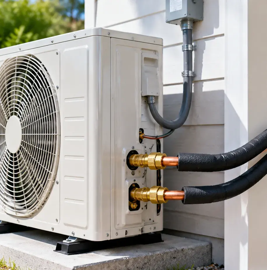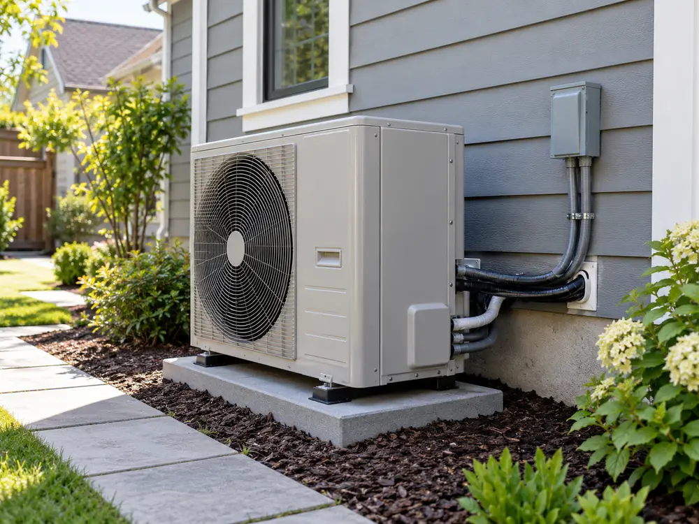
A heat pump schematic diagram shows how heat moves through a heat pump and how the main parts connect. Before you follow the lines and symbols, first check what kind of drawing you have. It may show the refrigerant cycle, the water-side piping (often called the hydronic system), the electrical controls, or the actual installation for one project. These drawings do different jobs, so do not use one as a substitute for another.
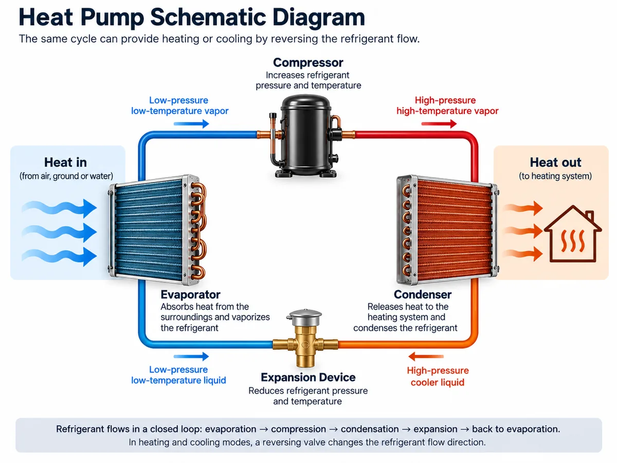
Start with four main parts. The evaporator picks up heat. The compressor raises refrigerant pressure and temperature. The condenser gives heat out. The expansion device then lowers the pressure so the refrigerant can go around the loop again. A reversible heat pump also uses a reversing valve to change the refrigerant path between heating and cooling. For real product selection, piping or wiring, we then check the exact model documents and your project conditions.
- Simple four-step heat pump cycle
- Heating vs cooling
- Heat pump schematic vs installation diagram
- How system type changes the drawing
- Monobloc vs split
- Air-to-water system diagram
- Electrical schematic
- What Airproz checks before recommending a heat pump
- Match the diagram to the right heat pump direction
- What to send us for product selection and a quotation
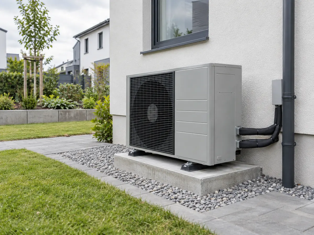
Simple Heat Pump Schematic Diagram: Follow the Four-Step Cycle
Most heat pumps use a closed refrigerant loop called a vapor-compression cycle. The simplest path is evaporator → compressor → condenser → expansion device → evaporator. The U.S. Department of Energy explains the same basic idea: a heat pump moves heat instead of creating heat at the point of use. Real units also have valves, sensors, fans, pumps and controls, but these four main functions are still easy to recognize.
| Stage | What happens | What to look for on the diagram |
|---|---|---|
| 1. Evaporation | Low-pressure refrigerant picks up heat and changes into vapor. | Find the heat exchanger that takes heat from the source. |
| 2. Compression | The compressor raises refrigerant pressure and temperature. | Follow the hot discharge line leaving the compressor. |
| 3. Condensation | Hot refrigerant gives heat out and changes back toward liquid. | Find the heat exchanger that sends useful heat to the building in heating mode. |
| 4. Expansion | The expansion device drops refrigerant pressure before the next cycle. | Look for the pressure drop before refrigerant returns to the evaporator. |
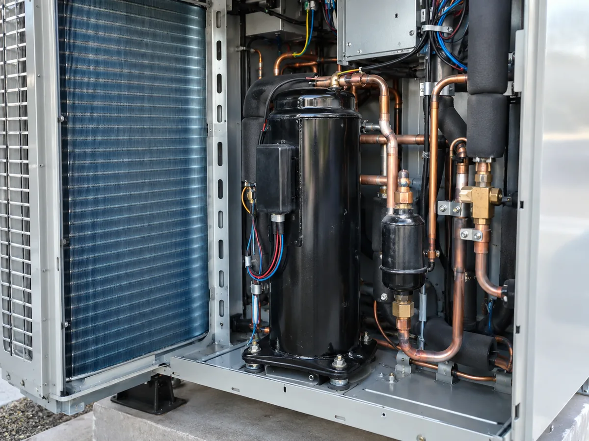
The SEAI Heat Pump Technology Guide explains the same four-stage cycle. It also shows why the temperature difference between the heat source and the required output matters. Engineers often call this difference temperature lift. A larger lift usually makes the compressor work harder. This is why a simple diagram cannot prove real project efficiency or heating output. When needed, we also check the coefficient of performance (COP), which shows heat output compared with electricity input at a stated test condition.
Heating vs Cooling: What Actually Changes?
In many reversible heat pumps, a reversing valve changes the refrigerant path. This makes the indoor and outdoor heat exchangers swap jobs between heating and cooling. The compressor still does the same basic job in both modes: it compresses the refrigerant. It does not simply run backward. When you read the diagram, check the arrows first and see which heat exchanger is taking in heat and which one is giving heat out.
| Part | Heating mode | Cooling mode |
|---|---|---|
| Outdoor heat exchanger | Usually picks up heat from outdoor air. | Usually releases heat outdoors. |
| Indoor / building heat exchanger | Releases useful heat to the building. | Picks up heat from the building. |
| Compressor | Raises refrigerant pressure and temperature. | Still raises refrigerant pressure and temperature. |
| Reversing valve | Sets the refrigerant path for heating. | Changes the path for cooling. |

If a diagram makes it look as if cooling happens because the compressor runs backward, do not use that reading. We check the refrigerant path, reversing-valve operation and the selected unit’s own documents before we use a schematic for a real project.
Defrost is normal in cold, damp weather
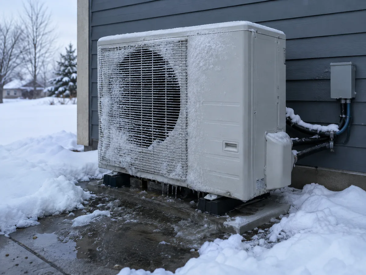
In cold and damp weather, frost can build up on the outdoor heat exchanger while the heat pump is heating. Many air-source heat pumps briefly change operation to remove that frost. This is called defrost. During defrost, the arrows on a simple heating diagram may not match what the system is doing every minute. Water volume, stored heat, controls, drainage and freeze protection can then become important.
A system can look correct on a simple drawing and still have winter problems. Defrost water may not drain properly, outdoor water pipes may freeze, or the system may not have enough water volume for stable operation. For cold-climate air-to-water projects, we check these points against the selected heat pump’s actual requirements.
Heat Pump Schematic vs Installation Diagram: Which One Do You Need?
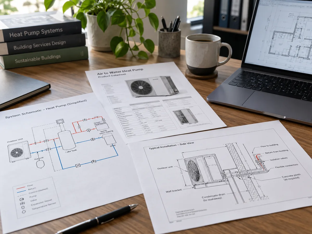
A heat pump schematic and a heat pump installation diagram are not the same document. A schematic explains how the system works or how parts connect. An installation drawing shows how the selected equipment fits a real site. Start with the question you need to answer. A refrigeration-cycle schematic shows how refrigerant moves heat. A hydronic diagram shows the water-side piping. An electrical schematic shows power and controls. A project installation drawing adds real equipment positions, routes, access and site details.
| Your question | Start with | What it shows | What you still need |
|---|---|---|---|
| How does a heat pump work? | Refrigeration-cycle schematic | Main parts, refrigerant path and heat-transfer logic. | Exact piping, refrigerant service details and wiring. |
| How does it connect to the building? | Hydronic / water-side schematic | Supply and return pipes, pumps, tanks, heat emitters and branches. | Final pipe sizes, pump sizing and exact model data. |
| Monobloc or split? | System architecture diagram | Where refrigerant stays and where water pipes run. | Climate, site, installer and service conditions before making the final choice. |
| How is power or control connected? | Exact-model electrical schematic | The power and control connections for that model. | Do not replace it with a generic internet wiring sheet. |
| How should this site be installed? | Project installation drawing | Actual routes, equipment positions, access and trade coordination. | The manufacturer limits and instructions for the selected equipment. |

As you move from “how it works” to a real installation, the documents must become more specific. We start with the simple concept. Then we check the exact model data. The approved project drawing comes after that. This keeps an educational diagram from being mistaken for installation instructions.
Why Different Heat Pump Types Need Different Diagrams
The same four refrigeration steps appear in many heat pumps, but the heat source and the building side can be very different. That changes the piping, controls and installation details. Two heat pumps can work on the same basic principle and still need very different drawings.
| System type | Where heat comes from | Where useful heating/cooling goes | What else the diagram may need |
|---|---|---|---|
| Air-to-air | Outdoor air | Indoor air | Indoor units, airflow or ductwork. |
| Air-to-water | Outdoor air | Water for space heating, cooling or domestic hot water (DHW), when the design supports it | Pumps, valves, radiators or underfloor heating, storage and freeze protection. |
| Ground-source | Ground loop or borehole | Building air or water | Ground-loop flow, pumps, antifreeze and loop/borehole design. |
| Water-source | A water body, groundwater or a shared water loop | Building air or water | Source-water flow, water quality and heat-exchanger arrangement. |
If your project is air-to-water, our air-to-water heat pump diagram guide shows that system in more detail. We keep that topic separate so this page can stay focused on how to read heat pump schematics in general.
Monobloc vs Split Heat Pump Diagram: What Changes?
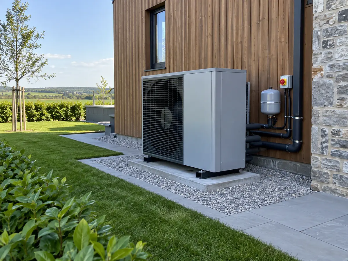
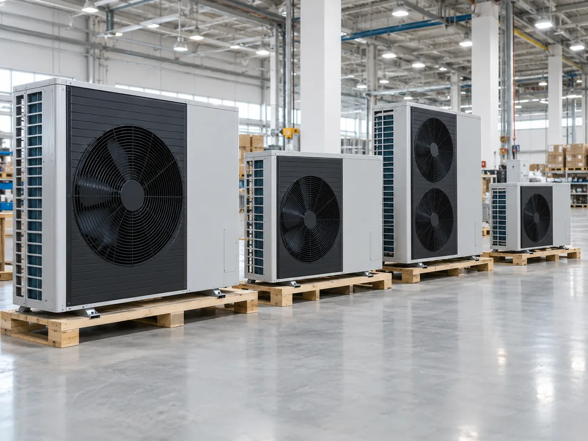
The main question is simple: where does the refrigerant stay, and where does the water travel? In a typical monobloc air-to-water heat pump, the main refrigerant circuit stays inside the packaged outdoor unit. Water pipes then run between the unit and the building. In a split system, refrigerant pipes normally run between an outdoor unit and an indoor refrigerant-side module. This changes the work needed on site, freeze risk, pipe routing and the documents we need to check.
| What to compare | Monobloc | Split |
|---|---|---|
| Refrigerant piping on site | Usually limited outside the packaged unit. | Usually runs between the outdoor and indoor sections. |
| Water pipes outdoors | Can create a serious freeze-protection issue in cold climates. | Depends on the water-side layout. |
| Work needed on site | Mostly water-side installation work. | Both refrigerant and water-side work can matter. |
| Documents to check | Water-side, electrical, control and installation documents. | Refrigerant, water-side, electrical, control and installation documents. |
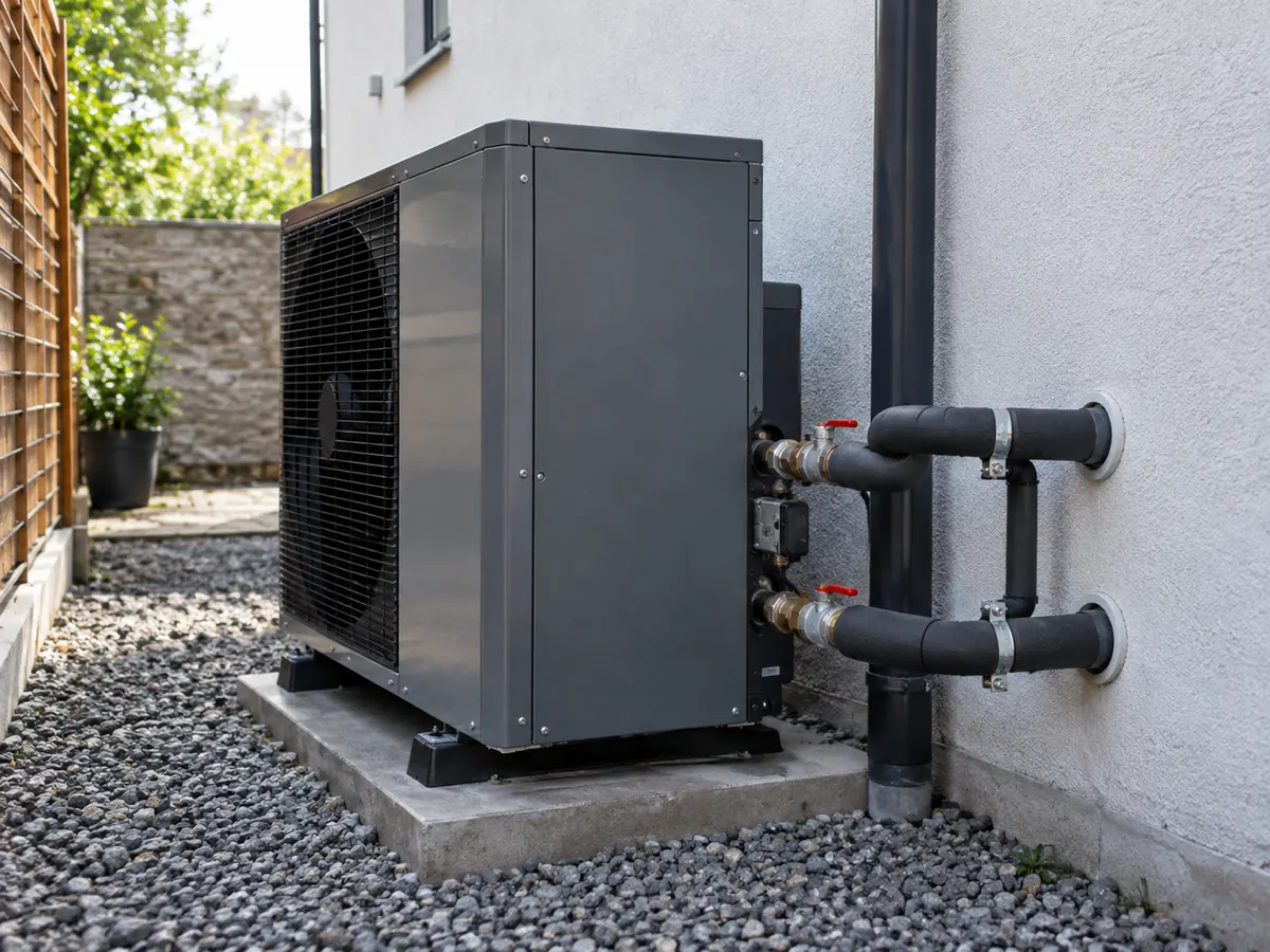
We do not choose monobloc or split just because one diagram looks simpler. We first check the climate, freeze risk, pipe route, installer capability, power supply, service access and building layout. Once those conditions are clear, you can review our space-heating heat pump range in the right project context.
Send us the application, the outdoor temperature used for sizing (design ambient temperature), the water or air temperature you need, the power supply and any important installation limits. We can use this information to narrow the system direction and tell you which technical documents to check next.
Air-to-Water Heat Pump System Diagram: Two Circuits, Not One
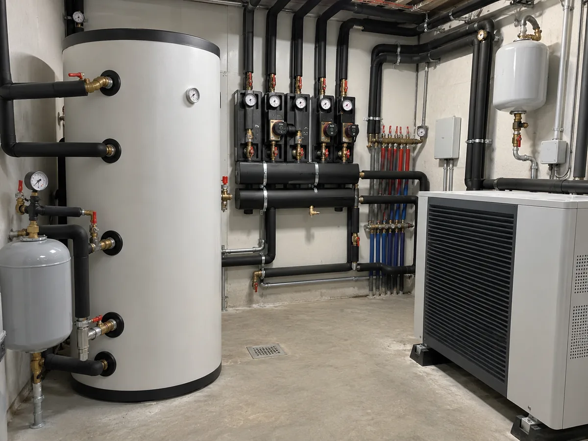
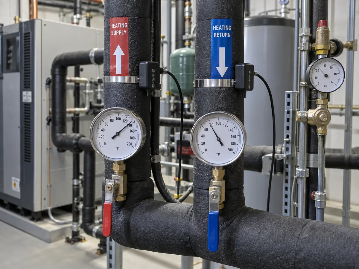
An air-to-water heat pump is much easier to understand when you separate the two fluid loops. Refrigerant moves heat inside the heat pump. Water then carries that heat to radiators, underfloor heating, fan coils or a domestic hot water system when the selected equipment supports those loads. The refrigerant and water exchange heat through a heat exchanger. They do not mix into one fluid loop.
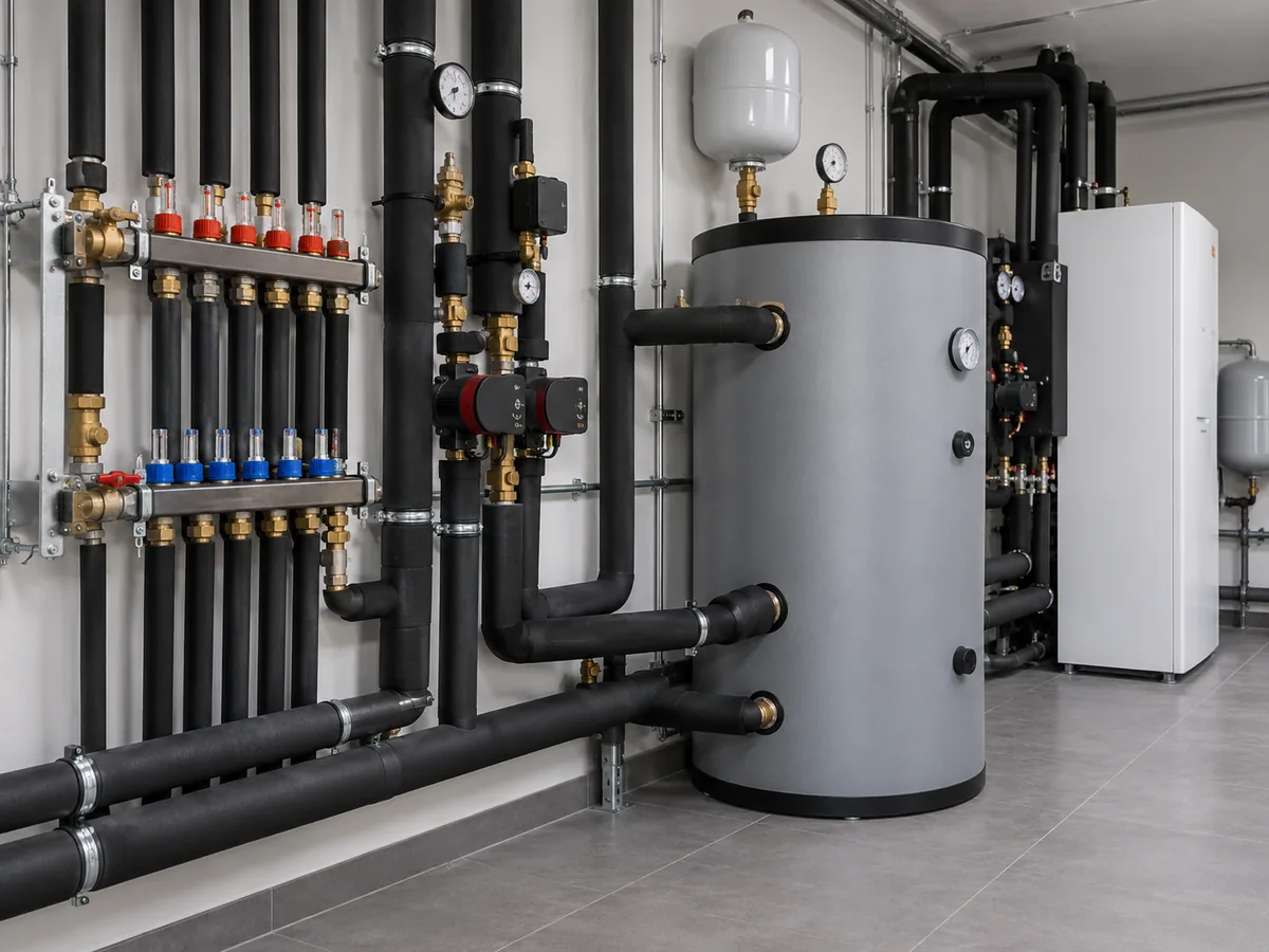
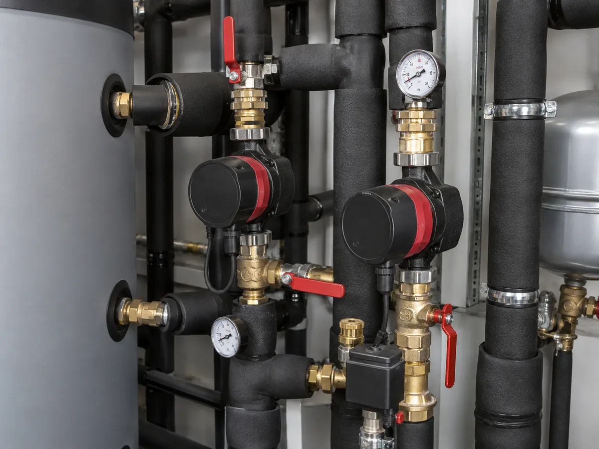
The water-side layout can be simple, or it may use a buffer tank. A buffer tank is a vessel that adds water volume and can help with minimum flow, cycling, defrost or hydraulic separation when the design needs it.
| Water-side layout | When it can work | Main risk | What we check |
|---|---|---|---|
| Direct loop | Flow and water volume stay stable without extra separation. | Closing zones or valves can reduce flow too much. | Minimum flow, water volume and pressure loss through radiators, underfloor heating or fan coils. |
| Series buffer tank | The system needs more water volume or help reducing short cycling. | An unnecessary tank adds cost and can increase pumping work. | Water volume, defrost needs, cycling and pump head. |
| Hydraulic separation / parallel buffer | The heat-pump flow and building flow need to work independently. | Mixing and extra pumping can reduce useful water temperature or efficiency. | Flow balance, pump interaction and supply/return temperatures. |
A buffer tank is not automatically required in every air-to-water system. We first ask what job the tank needs to do: protect minimum flow, add water volume, reduce cycling, help defrost, separate two water circuits or support zoning. Then we compare that need with the selected heat pump and the real piping design. For the operating principle, see how an air-to-water heat pump works.
Heat Pump Electrical Schematic: Use It to Understand the Connections
A generic electrical schematic can show how site power, the heat pump, controller, sensors, pumps, valves, backup heat and other accessories connect. This is useful for understanding the system. It is not enough for field wiring. Terminal names, electrical protection, control boards and optional connections can change between models and versions.
The manufacturer’s own documents show why the exact model matters. For example, a model-specific Trane installer guide includes terminal and setup information for specific equipment. We use this only as an example of document type. We never copy another manufacturer’s terminal layout into an Airproz project.
- Confirm the exact model and the latest drawing revision.
- Confirm voltage, phase and frequency.
- Confirm the controller, auxiliary heater, pumps, valves and other installed options.
- Confirm the thermostat or building management system (BMS) connection your project needs.
- Follow the selected equipment instructions, the project electrical design and local requirements.
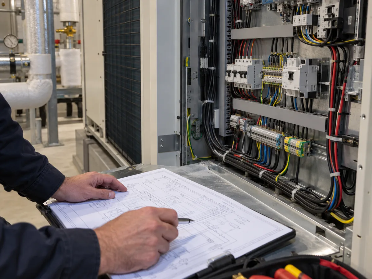
Once the system direction and exact model are clear, send us the voltage, phase, controller and installed options. We can then identify which model-specific performance, piping, electrical and control documents should be checked for that project. Availability depends on the selected equipment and market, so we confirm the applicable document set instead of using a generic wiring sheet.
Never wire a heat pump from a generic web diagram. Our heat pump thermostat wiring guide can help you understand thermostat terminals and control logic. Before any field wiring, return to the exact documents for the unit being installed.
What a Heat Pump Schematic Cannot Tell You
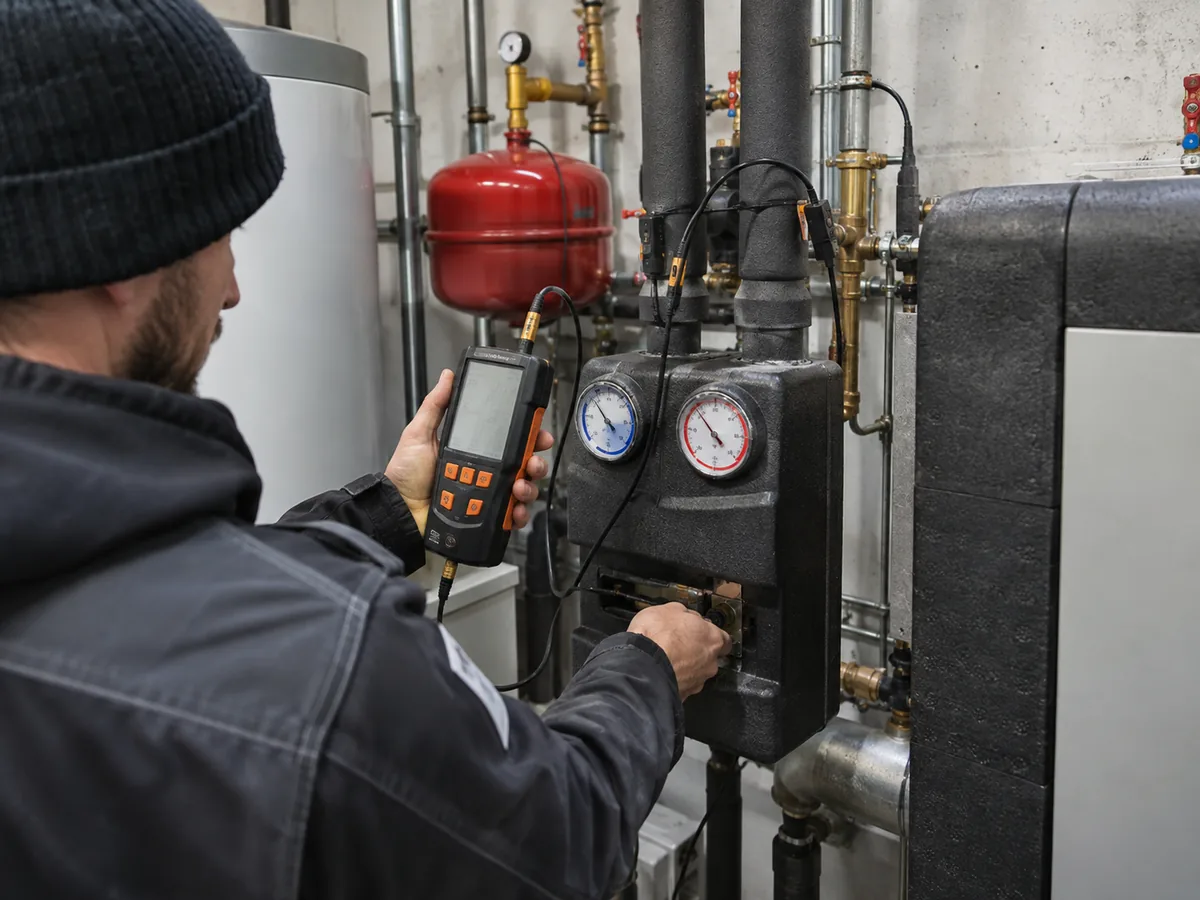
A clean diagram can explain how the parts relate to each other. It cannot prove how much heat a unit will deliver, or how efficiently it will run, at your real design condition. A number on a drawing or datasheet only has meaning when you know the conditions behind it. Before we recommend a unit, we match the diagram with verified performance data.
| The drawing or datasheet may show | It does not prove | What we check instead |
|---|---|---|
| The unit can heat and cool. | How much heating or cooling it can deliver at your project design condition. | Performance data at the outdoor/source temperature and delivery temperature your project needs. |
| A rated capacity is published. | That the rated value matches the building load on the coldest or hottest design day. | Calculated building load plus capacity at the real design point. |
| An operating range is published. | Full rated output across the whole operating range. | Capacity and control limits at the actual operating point. |
| A maximum leaving-water temperature is listed. | How much capacity or efficiency remains at that maximum temperature. | Performance data at the required water temperature. Engineers call the water temperature leaving the heat pump the leaving-water temperature (LWT). |
| A COP value is listed. | Efficiency over the whole heating season. | The COP test condition plus the seasonal coefficient of performance (SCOP) and its stated conditions. |
| A line connects two components. | Actual pipe size, wire size, pressure drop or allowed route length. | Exact model instructions plus the project mechanical and electrical calculations. |
We keep single-point efficiency and seasonal efficiency separate. ENERGY STAR heat-pump criteria also tie performance numbers to defined test conditions. A COP value applies to a stated operating point. SCOP describes seasonal performance under its defined method. Neither a maximum water temperature nor an operating limit proves full heating output at that condition.
Common Heat Pump Diagram Mistakes That Cause Real Problems
Most mistakes happen when someone uses the right type of drawing for the wrong job. We check the points below early because they can change the equipment choice, installation plan or documents needed next.
| Common mistake | What can go wrong | What Airproz checks |
|---|---|---|
| Using a simple functional schematic as a construction drawing | Pipe routes, clearances, drainage or trade responsibilities may be wrong. | Exact equipment dimensions, connection points and project layout. |
| Mixing the refrigerant loop with the water loop | Pumps, valves, pipework or freeze risk may be understood incorrectly. | Which fluid is in each loop and where the two loops exchange heat. |
| Assuming the compressor reverses for cooling | The cooling cycle is read incorrectly. | Reversing-valve routing and the job of each heat exchanger. |
| Copying electrical terminals from another model | This can cause control faults or unsafe wiring. | Exact model, current document, power supply and installed options. |
| Adding every tank, pump or valve seen in an online diagram | The system can become more expensive or harder to control. | What job each component actually needs to do. |
| Reading diagram colors as real measured values | A concept color may be mistaken for real pressure or temperature. | Actual instruments, commissioning readings and verified product documents. |
What Airproz Checks Before We Recommend a Heat Pump
A schematic helps us understand the system, but it is only the starting point. Before we narrow the product family or model, we check the project information that can change heating output, efficiency, water-side design, electrical compatibility and installation.

| What we need from your project | Why it matters | What it can change |
|---|---|---|
| Calculated heating / cooling load | Floor area alone cannot tell us the required capacity. | Product family and capacity options. |
| Outdoor or source temperature used for sizing | Heat-pump output changes as operating conditions change. | Heating/cooling output at the design point and the safety margin. |
| Required water or supply-air temperature | A higher delivery temperature usually makes the heat pump work harder. | Capacity, efficiency and which system type is suitable. |
| Voltage, phase and frequency | The heat pump must match the available electrical supply. | Available model/configuration and electrical documents. |
| Monobloc or split installation limits | They change where refrigerant and water pipes run. | Installer work, freeze protection and pipe route. |
| Radiators, underfloor heating, fan coils, DHW and zoning | Different loads need different temperatures, flow rates and controls. | Water-side layout, storage and control setup. |
| Thermostat or BMS requirements | The controller must match the interface your project uses. | Controller, gateway and wiring documents. |
| Target country and quantity | Market requirements and order scope can change the product and document path. | Product/document options and quotation scope. |

A rated capacity is not automatically the capacity you will get on the coldest design day. An operating range does not mean full output across that whole range. A maximum leaving-water temperature also does not prove full capacity at that temperature. We use your real project conditions to decide which product data matters before we recommend an exact setup.
In real air-to-water projects, a drawing can look correct while the product choice is still wrong. One common reason is checking capacity only at a mild rating point instead of the project design outdoor temperature and the required leaving-water temperature (LWT). That is why we read design ambient temperature and LWT together before we narrow the equipment direction.
Match the Diagram to the Right Heat Pump Direction
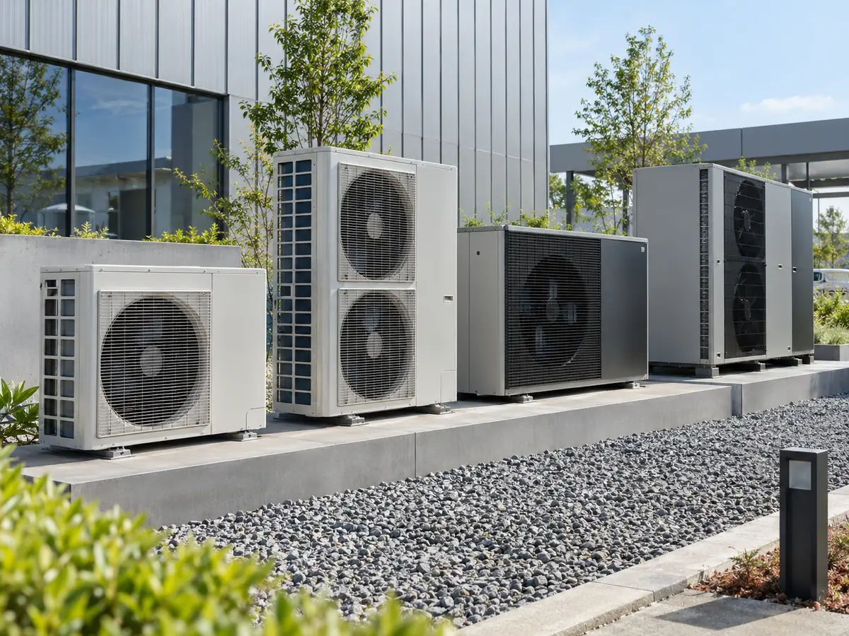
Once the system diagram is clear, the next step is not to guess an exact model. We first match the project to the right product direction, then check the operating conditions that can change the final selection.
| Your project | Start with | What Airproz checks next |
|---|---|---|
| Underfloor heating or low-temperature hydronic heating | Air-to-water space-heating heat pumps | Calculated load, design ambient temperature, required LWT and flow conditions. |
| Radiator heating | Air-to-water heat pump direction | Required radiator water temperature, design load and available heat-emitter output. |
| Space heating plus domestic hot water (DHW) | Heating/DHW system direction | Space-heating load, DHW demand, tank arrangement and required water temperatures. |
| Monobloc layout | Monobloc product family | Freeze exposure, outdoor water piping, pipe route, service access and installer conditions. |
| Split architecture | Project engineering review | Refrigerant route, indoor/outdoor arrangement, installer scope and service conditions. |
| Thermostat or BMS-controlled project | Compatible control direction | Required interface, controller, gateway, I/O and the wiring documents that apply. |
Send us the project load, design ambient temperature, required water temperature, power supply and installation limits. We can use those conditions to narrow the product family before exact model selection. View our space-heating heat pump range or send the project conditions to Airproz.
From Heat Pump Diagram to Product Selection, Technical Documents and RFQ
If you need a request for quotation (RFQ), you do not need to finish the whole system design first. Start with the system type and the real operating conditions. We can then compare the right product family, check the model data that matters and identify which technical documents should control the next step. The final project drawing comes later, after the main equipment and connections are known.
- Define the system: air-to-water or air-to-air, heating-only or reversible, monobloc or split, and whether domestic hot water is needed.
- Define the operating conditions: heating/cooling load, outdoor or source temperature used for sizing, and the water or air temperature you need.
- Define the connections: power supply, radiators/underfloor heating/fan coils, DHW, zoning, thermostat/BMS, pipe routes and service limits.
- Match the product and documents: we can then narrow the equipment options and identify the performance, water-side, electrical, dimensional and control documents that matter.
Minimum information to send Airproz
- Application and system type, if you already know them.
- Calculated heating/cooling load, or the best design information you have.
- Outdoor or source temperature used for sizing.
- Required leaving-water or supply-air temperature.
- Voltage, phase and frequency.
- Monobloc/split preference or any installation limits.
- Radiators, underfloor heating, fan coils or other loads; DHW need; zoning; and any known storage or backup-heat requirement.
- Thermostat or BMS requirements, if relevant.
- Target country or market, quantity and any drawings you already have.
You do not need to turn a generic schematic into a final design before you contact us. Send the project information you already have. We can narrow the equipment direction, point out the missing technical inputs and identify which model-specific performance, piping, electrical, dimensional or control documents should be checked next. Once the system direction is confirmed, ask us which applicable technical documents are available for the selected equipment and market. Send your project conditions to Airproz.
Heat Pump Diagram FAQ

Start with the evaporator, compressor, condenser and expansion device. Then check which heat exchanger is picking up heat and which one is giving heat out in the operating mode you are looking at.
A reversing valve changes the refrigerant path so the main heat exchangers swap jobs. The compressor still compresses the refrigerant; it does not simply run backward.
No. A generic diagram can help you understand the connections, but field wiring must follow the exact model and current manufacturer documents, the project power supply, installed options and local requirements.
No. A buffer tank is only useful when the system needs the job it performs. The need can depend on minimum flow, water volume, zoning, defrost, cycling, heat emitters, controls and the selected heat pump requirements.
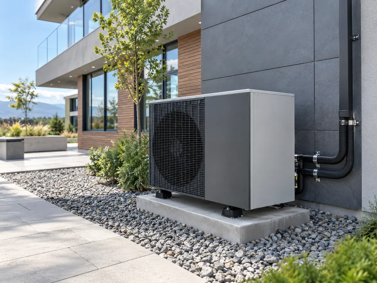
A monobloc diagram usually keeps the main refrigerant circuit inside the packaged outdoor unit, so water pipes run toward the building. A split system normally has refrigerant pipes between the outdoor and indoor sections. The exact layout still depends on the selected equipment.
A schematic explains how the parts work together. A project installation drawing shows the real equipment positions, piping, electrical connections, controls, drainage, access and site responsibilities for one project.
Technical scope: this guide helps you understand heat pump schematics, compare system layouts and prepare the information needed for product selection. Refrigerant service, electrical work, final water-side design, installation and commissioning must follow the current documents for the selected equipment, the approved project design and local requirements.
Technical references: U.S. Department of Energy — Heat Pump Systems; SEAI — Heat Pumps Technology Guide; ENERGY STAR — Heat Pump Equipment Key Product Criteria; and a model-specific Trane Installer’s Guide, used only to show why electrical documents must match the exact equipment.